AUDIO AND VISUAL SYSTEM(w/o Navigation System), Diagnostic DTC:B15C3
| DTC Code | DTC Name |
|---|---|
| B15C3 | Speaker Output Short |
DESCRIPTION
This DTC is stored when a malfunction occurs in the speakers.
DTC No. |
Detection Item |
DTC Detection Condition |
Trouble Area |
|---|---|---|---|
B15C3 |
Speaker Output Short |
A short is detected in the speaker output circuit. |
|
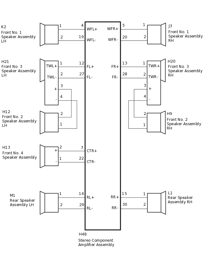
WIRING DIAGRAM
PROCEDURE
CLEAR DTC
Clear the DTCs.
Body Electrical > Navigation System > Clear DTCs
Result
Proceed
NEXT
CHECK FOR DTC
Recheck for DTCs and check if the same DTC is output again.
Body Electrical > Navigation System > Trouble Codes
OK
DTC B15C3 is not output.
Result
Proceed
OK
NG
CHECK HARNESS AND CONNECTOR
*1: for RH Side
*2: for LH Side
Disconnect the H48 stereo component amplifier assembly connector.
Disconnect the J3*1 and/or K2*2 front No. 1 speaker assembly connector.
Disconnect the H9*1 and/or H12*2 front No. 2 speaker assembly connector.
Disconnect the H13 front No. 4 speaker assembly connector.
Disconnect the L1*1 and/or M1*2 rear speaker assembly connector.
Measure the resistance according to the value(s) in the table below.
Standard Resistance
for RH Side
Tester Connection
Condition
Specified Condition
H48-5 (WFR+) - J3-1
Always
Below 1 Ω
H48-20 (WFR-) - J3-2
Always
Below 1 Ω
H48-13 (FR+) - H20-1 (TWR+)
Always
Below 1 Ω
H48-28 (FR-) - H20-2 (TWR-)
Always
Below 1 Ω
H20-3 (+) - H9-2
Always
Below 1 Ω
H20-4 (-) - H9-1
Always
Below 1 Ω
H48-15 (RR+) - L1-1
Always
Below 1 Ω
H48-30 (RR-) - L1-2
Always
Below 1 Ω
H48-5 (WFR+) - Body ground
Always
10 kΩ or higher
H48-20 (WFR-) - Body ground
Always
10 kΩ or higher
H48-13 (FR+) - Body ground
Always
10 kΩ or higher
H48-28 (FR-) - Body ground
Always
10 kΩ or higher
H20-3 (+) - Body ground
Always
10 kΩ or higher
H20-4 (-) - Body ground
Always
10 kΩ or higher
H48-15 (RR+) - Body ground
Always
10 kΩ or higher
H48-30 (RR-) - Body ground
Always
10 kΩ or higher
Table 1. for LH Side: Tester Connection
Condition
Specified Condition
H48-4 (WFL+) - K2-1
Always
Below 1 Ω
H48-19 (WFL-) - K2-2
Always
Below 1 Ω
H48-12 (FL+) - H21-1 (TWL+)
Always
Below 1 Ω
H48-27 (FL-) - H21-2 (TWL-)
Always
Below 1 Ω
H21-3 (+) - M1-2
Always
Below 1 Ω
H21-4 (-) - M1-1
Always
Below 1 Ω
H48-14 (RL+) - M1-1
Always
Below 1 Ω
H48-29 (RL-) - M1-2
Always
Below 1 Ω
H48-4 (WFL+) - Body ground
Always
10 kΩ or higher
H48-19 (WFL-) - Body ground
Always
10 kΩ or higher
H48-12 (FL+) - Body ground
Always
10 kΩ or higher
H48-27 (FL-) - Body ground
Always
10 kΩ or higher
H21-3 (+) - Body ground
Always
10 kΩ or higher
H21-4 (-) - Body ground
Always
10 kΩ or higher
H48-14 (RL+) - Body ground
Always
10 kΩ or higher
H48-29 (RL-) - Body ground
Always
10 kΩ or higher
Table 2. for Center Side: Tester Connection
Condition
Specified Condition
H48-7 (CTR+) - H13-2 (+)
Always
Below 1 Ω
H48-22 (CTR-) - H13-1 (-)
Always
Below 1 Ω
H48-7 (CTR+) - Body ground
Always
10 kΩ or higher
H48-22 (CTR-) - Body ground
Always
10 kΩ or higher
Result
Proceed to
OK
NG
NG REPAIR OR REPLACE HARNESS OR CONNECTOR
INSPECT FRONT NO. 1 SPEAKER ASSEMBLY
Remove the front No. 1 speaker assembly.
Inspect the front No. 1 speaker assembly.
Result
Proceed to
OK
NG
INSPECT FRONT NO. 2 SPEAKER ASSEMBLY
Remove the front No. 2 speaker assembly.
Inspect the front No. 2 speaker assembly.
Result
Proceed to
OK
NG
CHECK FRONT NO. 3 SPEAKER ASSEMBLY
Replace the front No. 3 speaker assembly with a known good one.
Check for DTCs and check if the same DTC is output.
Body Electrical > Navigation System > Trouble Codes
OK
No DTCs are output.
Result
Proceed to
OK
NG
OK END (FRONT NO. 3 SPEAKER ASSEMBLY IS DEFECTIVE)
INSPECT FRONT NO. 4 SPEAKER ASSEMBLY
Remove the front No. 4 speaker assembly.
Inspect the front No. 4 speaker assembly.
Result
Result
OK
NG
INSPECT REAR SPEAKER ASSEMBLY
Remove the rear speaker assembly.
Inspect the rear speaker assembly.
Result
Proceed to
OK
NG