WIRELESS DOOR LOCK CONTROL SYSTEM (for Built-in Type Door Control Receiver) TERMINALS OF ECU
-
CHECK THEFT WARNING ECU ASSEMBLY (except 2 Step Unlock Function)

-
Disconnect the T36 theft warning ECU assembly connector.
-
Measure the resistance and voltage according to the value(s) in the table below.
Terminal No. (Symbol) Wiring Color Terminal Description Condition Specified Condition T36-1 (E) - Body ground B-W - Body ground Ground Always Below 1 Ω T36-4 (+B1) -T36-1 (E) L-Y - B-W Battery power supply Always 11 to 14 V T36-14 (+B2) - T36-1 (E) G - B-W Battery power supply Always 11 to 14 V T36-18 (IG) - T36-1 (E) R-L - B-W Ignition power supply Ignition switch off Below 1 V Ignition switch ON 11 to 14 V
-
If the result is not as specified, there may be a malfunction on the wire harness side.
-
-
Reconnect the T36 theft warning ECU assembly connector.
-
Measure the resistance and voltage according to the value(s) in the table below.
Terminal No. (Symbol) Wiring Color Terminal Description Condition Specified Condition T36-3 (DMLP) - Body ground* P - Body ground Interior lights output signal Interior lights on Below 1 V Interior lights off 11 to 14 V T36-5 (KSW) - Body ground G-Y - Body ground Unlock warning switch input signal No key in ignition key cylinder 10 kΩ or higher Key inserted in ignition key cylinder Below 1 Ω T36-7 (CTY) - Body ground R-L - Body ground All door courtesy switches input signal One or more doors are open Below 1 V All doors are closed 11 to 14 V T36-13 (SH-) - Body ground B - Body ground Security horn output signal Security horn assembly off Below 1 V Security horn assembly on Pulse generation T36-25 (L2) - Body ground L - Body ground Door lock output signal Ignition switch off, all doors closed and transmitter switch not pressed Below 1 V Ignition switch off, all doors closed and transmitter lock switch pressed Pulse generation T36-26 (UL3) -Body ground L-W - Body ground Door unlock output signal Ignition switch off, all doors closed and transmitter switch not pressed Below 1 V Ignition switch off, all doors closed and transmitter unlock switch pressed Pulse generation T36-28 (HAZD) - Body ground G-O -Body ground All hazard warning light output signals Hazard warning signal switch assembly off 11 to 14 V Hazard warning signal switch assembly on Below 1 V
-
*: w/ Illuminated Entry Function
-
If the result is not as specified, the theft warning ECU assembly may have a malfunction.
-
-
-
CHECK THEFT WARNING ECU ASSEMBLY (for 2 Step Unlock Function)

-
Disconnect the T39 theft warning ECU assembly connector.
-
Measure the resistance and voltage according to the value(s) in the table below.
Terminal No. (Symbol) Wiring Color Terminal Description Condition Specified Condition T39-1 (E) - Body ground W-B - Body ground Ground Always Below 1 Ω T39-3 (+B1) -T39-1 (E) L-Y - W-B Battery power supply Always 11 to 14 V T39-4 (IG) - T39-1 (E) R-L - W-B Ignition power supply Ignition switch off Below 1 V Ignition switch ON 11 to 14 V T39-12 (+B2) - T39-1 (E) LG - W-B Battery power supply Always 11 to 14 V
-
If the result is not as specified, there may be a malfunction on the wire harness side.
-
-
Reconnect the T39 theft warning ECU assembly connector.
-
Measure the resistance and voltage according to the value(s) in the table below.
Terminal No. (Symbol) Wiring Color Terminal Description Condition Specified Condition T39-2 (DMLP) - Body ground* P - Body ground Interior lights output signal Interior lights on Below 1 V Interior lights off 11 to 14 V T39-5 (KSW) - Body ground G-Y - Body ground Unlock warning switch input signal No key in ignition key cylinder 10 kΩ or higher Key inserted in ignition key cylinder Below 1 Ω T39-7 (CTY) - Body ground R-L - Body ground All door courtesy switches input signal One or more doors are open Below 1 V All doors are closed 11 to 14 V T39-20 (L2) - Body ground L - Body ground Door lock output signal Ignition switch off, all doors closed and transmitter switch not pressed Below 1 V Ignition switch off, all doors closed and transmitter lock switch pressed Pulse generation T39-21 (UL3) -Body ground L-W - Body ground Door unlock output signal Ignition switch off, all doors closed and transmitter switch not pressed Below 1 V Ignition switch off, all doors closed and transmitter unlock switch pressed Pulse generation T39-23 (HAZD) - Body ground G-O -Body ground All hazard warning light output signals Hazard warning signal switch assembly off 11 to 14 V Hazard warning signal switch assembly on Below 1 V T39-26 (SH-) - Body ground B - Body ground Security horn output signal Security horn assembly off Below 1 V Security horn assembly on Pulse generation
-
*: w/ Illuminated Entry Function
-
If the result is not as specified, the theft warning ECU assembly may have a malfunction.
-
-
-
CHECK DRIVER SIDE JUNCTION BLOCK ASSEMBLY (INTEGRATION RELAY)
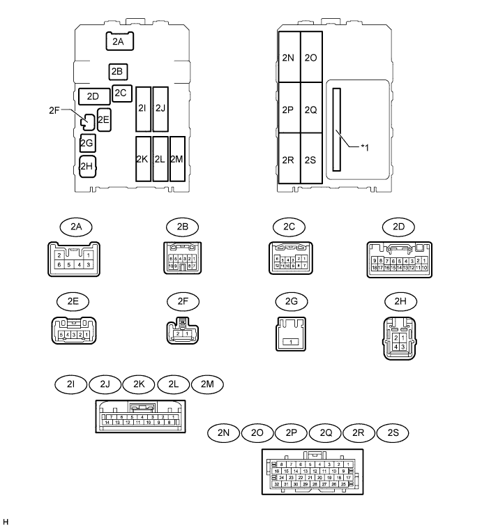
Text in Illustration *1 Integration Relay - -
-
Disconnect the 2A, 2D, 2H and 2L driver side junction block assembly connectors.
-
Measure the voltage and resistance according to the value(s) in the table below.
Terminal No. (Symbol) Wiring Color Terminal Description Condition Specified Condition 2D-9 (GND) - Body ground W-B - Body ground Ground Always Below 1 Ω 2D-18 (GND) - Body ground W-B - Body ground Ground Always Below 1 Ω 2H-4 (ALTB) - Body ground LG - Body ground Battery power supply Always 11 to 14 V 2L-12 (BECU) - 2D-9 (GND) L - W-B Battery power supply Always 11 to 14 V 2A-6 (SIG) - Body ground B-Y - Body ground Ignition switch Ignition switch off Below 1 V Ignition switch ON 11 to 14 V
-
If the result is not as specified, there may be a malfunction on the wire harness side.
-
-
Reconnect the 2A, 2D, 2H and 2L driver side junction block assembly connectors.
-
Measure the voltage and resistance according to the value(s) in the table below.
Terminal No. (Symbol) Wiring Color Terminal Description Condition Specified Condition 2A-4 (L1) - Body ground L - Body ground
-
Power window regulator master switch assembly (door control switch) lock input signal
-
Driver side door key-linked lock input signal
-
Power window regulator master switch assembly (door control switch) locked
-
Driver side door key cylinder in lock position
Below 1 V
-
Power window regulator master switch assembly (door control switch) off
-
Ignition switch off, all doors closed and driver side door key cylinder in neutral position
11 to 14 V 2D-4 (UL1) - Body ground L-W - Body ground
-
Power window regulator master switch assembly (door control switch) unlock input signal
-
Driver side door key-linked unlock input signal
-
Power window regulator master switch assembly (door control switch) unlocked
-
Driver side door key cylinder in unlock position
Below 1 V
-
Power window regulator master switch assembly (door control switch) off
-
Ignition switch off, all doors closed and driver side door key cylinder in neutral position
11 to 14 V 2E-3 (PCTY) - Body ground P - Body ground All courtesy light switches input signal One or more doors open Below 1 V All doors closed 11 to 14 V 2N-12 (ILE) - Body ground*1 P - Body ground Ignition key cylinder light output signal Ignition key cylinder light on Below 1 V Ignition key cylinder light off 11 to 14 V 2K-10 (ACT-) - Body ground L-Y - Body ground Door lock motor unlock drive output signal (passenger door and rear RH door*2, *4 or rear LH door*3, *4) Power window regulator master switch assembly (door control switch) not pushed and driver side door key cylinder in neutral position Below 1 V Lock side of power window regulator master switch assembly (door control switch) pushed, or driver side door key cylinder in unlock position 11 to 14 V 2K-11 (ACT+) - Body ground L - Body ground Door lock motor lock drive output signal (passenger door and rear RH door*2, *4 or rear LH door*3, *4) Power window regulator master switch assembly (door control switch) not pushed and driver side door key cylinder in neutral position Below 1 V Power window regulator master switch assembly (door control switch) or driver side door key cylinder in lock position 11 to 14 V 2O-10 (KSW) - Body ground G-Y - Body ground Unlock warning switch input signal No key in ignition key cylinder 10 kΩ or higher Key inserted in ignition key cylinder Below 1 Ω 2O-27 (DCTY) - Body ground R-B - Body ground Front door courtesy light switch assembly LH*2 or RH*3 input signal Driver side door open Below 1 V Driver side door closed 11 to 14 V 2R-27 (ACT-) - Body ground L-Y - Body ground Door lock motor unlock drive output signal (driver door, and rear LH door*2, *4 or rear RH door*3, *4) Power window regulator master switch assembly (door control switch) not pushed and driver side door key cylinder in neutral position Below 1 V Lock side of power window regulator master switch assembly (door control switch) pushed, or driver side door key cylinder in unlock position 11 to 14 V 2R-28 (ACT+) - Body ground L - Body ground Door lock motor LOCK drive output signal (driver door, and rear LH door*2, *4 or rear RH door*3, *4) Power window regulator master switch assembly (door control switch) not pushed and driver side door key cylinder in neutral position Below 1 V Lock side of power window regulator master switch assembly (door control switch) pushed, or driver side door key cylinder in unlock position 11 to 14 V
-
*1: w/ Illuminated Entry Function
-
*2: for LHD
-
*3: for RHD
-
*4: for Double Cab
-
If the result is not as specified, the driver side junction block assembly may have a malfunction.
-
-