VEHICLE STABILITY CONTROL SYSTEM, Diagnostic DTC:C1253
| DTC Code | DTC Name |
|---|---|
| C1253 | Pump Motor Relay |
DESCRIPTION
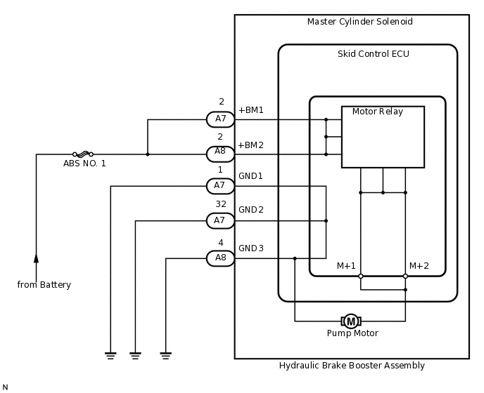
The motor relay (semiconductor relay) is built into the master cylinder solenoid and drives the pump motor based on a signal from the skid control ECU.
DTC No. |
Detection Item |
DTC Detection Condition |
Trouble Area |
|---|---|---|---|
C1253 |
Pump Motor Relay |
There is a motor system circuit (motor input circuit) malfunction. |
|
WIRING DIAGRAM
CAUTION / NOTICE / HINT
When replacing the master cylinder solenoid, perform calibration (Click here).
Inspect the fuses for circuits related to this system before performing the following inspection procedure.
PROCEDURE
PERFORM ACTIVE TEST USING INTELLIGENT TESTER (MOTOR RELAY)
Turn the engine switch off.
Connect the intelligent tester to the DLC3.
Turn the engine switch on (IG).
Turn the intelligent tester on.
Start the engine.
Enter the following menus: Chassis / ABS/VSC/TRC / Active Test.
Chassis > ABS/VSC/TRC > Active Test
Tester Display
Measurement Item
Control Range
Diagnostic Note
Motor Relay
Motor relay
Relay ON/OFF
An operating sound of the motor can be heard.
Check the operating sound of the motor individually when operating it with the intelligent tester.
OK
An operating sound of the motor can be heard.
Result
Result
OK
NG
NG CHECK TERMINAL VOLTAGE (+BM1, +BM2)Click here
RECONFIRM DTC
Clear the DTCs.
Chassis > ABS/VSC/TRC > Clear DTCs
Turn the engine switch off.
Depress the brake pedal more than 40 times.
Turn the engine switch on (IG).
Wait until the pump motor stops.
Depress the brake pedal several times until the pump motor turns on. (Procedure A)
Wait until the pump stops. (Procedure B)
Repeat the above steps (procedure A and B) 3 more times.
Check if the same DTC is output.
Tip:Reinstall the sensors, connectors, etc. and restore the previous vehicle conditions before rechecking for DTCs.
Result
Result
Proceed to
DTC is not output
A
DTC is output
B
Chassis > ABS/VSC/TRC > Trouble Codes
CHECK TERMINAL VOLTAGE (+BM1, +BM2)
Disconnect the A7 and A8 skid control ECU connectors.
-
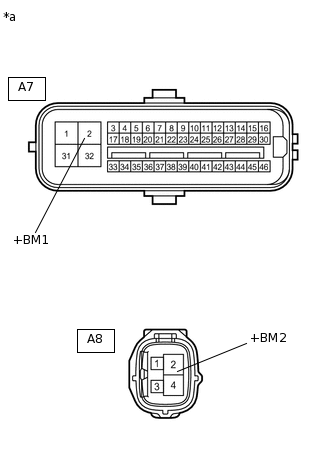
*a
Front view of wire harness connector
(to Skid Control ECU)
Measure the voltage according to the value(s) in the table below.
Standard Voltage
Tester Connection
Condition
Specified Condition
A7-2 (+BM1) - Body ground
Always
11 to 14 V
A8-2 (+BM2) - Body ground
Always
11 to 14 V
Result
Result
OK
NG
NG REPAIR OR REPLACE HARNESS OR CONNECTOR
CHECK HARNESS AND CONNECTOR (GND1, GND2 AND GND3 TERMINAL)
Disconnect the A7 and A8 skid control ECU connectors.
Measure the resistance according to the value(s) in the table below.
Standard Resistance
Tester Connection
Condition
Specified Condition
A7-1 (GND1) - Body ground
Always
Below 1 Ω
A7-32 (GND2) - Body ground
Always
Below 1 Ω
A8-4 (GND3) - Body ground
Always
Below 1 Ω
Result
Result
OK
NG
NG REPAIR OR REPLACE HARNESS OR CONNECTOR
RECONFIRM DTC
Clear the DTCs.
Chassis > ABS/VSC/TRC > Clear DTCs
Turn the engine switch off.
Depress the brake pedal more than 40 times.
Turn the engine switch on (IG).
Wait until the pump motor stops.
Depress the brake pedal several times until the pump motor turns on. (Procedure A)
Wait until the pump stops. (Procedure B)
Repeat the above steps (procedure A and B) 3 more times.
Check if the same DTC is output.
Tip:Reinstall the sensors, connectors, etc. and restore the previous vehicle conditions before rechecking for DTCs.
Result
Result
Proceed to
DTC is not output
A
DTC is output
B
Chassis > ABS/VSC/TRC > Trouble Codes