ENGINE ASSEMBLY REMOVAL

CAUTION / NOTICE / HINT

Note:

for Manual Transaxle:

When the transaxle is removed, be sure to use a new clutch release with bearing cylinder and new installation bolts. Removal of the transaxle allows the compressed clutch release with bearing cylinder to return to its original position, and dust could damage the seal of the clutch release with bearing cylinder, possibly causing clutch fluid leaks.

PROCEDURE

  1. DISCHARGE FUEL SYSTEM PRESSURE

  2. ALIGN FRONT WHEELS FACING STRAIGHT AHEAD

  3. REMOVE FRONT BUMPER COVER

    1. Remove the front bumper cover (Click here).

  4. REMOVE RADIATOR ASSEMBLY

    1. Remove the radiator (Click here).

  5. PRECAUTION

    Note:

    After turning the ignition switch off, waiting time may be required before disconnecting the cable from the battery terminal. Therefore, make sure to read the disconnecting the cable from the battery terminal notice before proceeding with work (Click here).

  6. DISCONNECT CABLE FROM NEGATIVE BATTERY TERMINAL

    Note:

    When disconnecting the cable, some systems need to be initialized after the cable is reconnected (Click here).

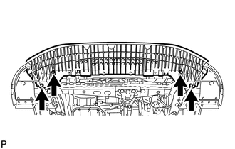
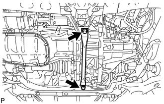
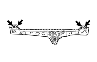
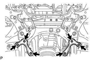
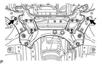
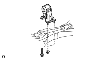
  7. REMOVE FRONT LOWER BUMPER ABSORBER

    1. A209991

      Remove the 4 bolts and front lower bumper absorber.

  8. REMOVE REAR ENGINE UNDER COVER RH

  9. REMOVE REAR ENGINE UNDER COVER LH

    1. Remove the 5 clips and under cover.

  10. REMOVE CENTER NO. 4 ENGINE UNDER COVER

    1. A207261

      Remove the 2 clips and under cover.

  11. REMOVE NO. 2 ENGINE UNDER COVER

    1. A197474

      Remove the 4 clips and under cover.

  12. DRAIN ENGINE COOLANT

  13. DRAIN ENGINE OIL

  14. DRAIN MANUAL TRANSAXLE OIL

  15. DRAIN CONTINUOUSLY VARIABLE TRANSAXLE FLUID

  16. DISCONNECT RADIATOR RESERVOIR ASSEMBLY

    1. A204819

      Remove the 2 bolts and disconnect the radiator reservoir.

    2. Remove the grommet from the radiator reservoir.

  17. REMOVE V-RIBBED BELT

  18. REMOVE GENERATOR ASSEMBLY

  19. DISCONNECT NO. 2 RADIATOR HOSE

    1. A206129

      Disconnect the radiator hose from the water inlet.

  20. DISCONNECT DISCHARGE HOSE SUB-ASSEMBLY (w/ Air Conditioning System)

  21. DISCONNECT SUCTION HOSE SUB-ASSEMBLY (w/ Air Conditioning System)

  22. DISCONNECT COMPRESSOR WITH PULLEY ASSEMBLY (w/ Air Conditioning System)

    1. E175924

      Disconnect the connector.

    2. Remove the 2 bolts and 2 nuts.

    3. E175927

      Using an E8 "TORX" socket wrench, remove the 2 stud bolts and disconnect the compressor assembly with pulley.

  23. REMOVE AIR CLEANER CAP SUB-ASSEMBLY

  24. REMOVE AIR CLEANER CASE SUB-ASSEMBLY

  25. REMOVE BATTERY CLAMP SUB-ASSEMBLY

    1. U123712

      Disconnect the cable from the positive (+) battery terminal.

    2. Remove the bolt and loosen the nut.

    3. Remove the battery clamp.

  26. REMOVE BATTERY

  27. REMOVE BATTERY TRAY

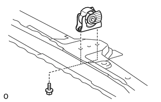
  28. REMOVE BATTERY CARRIER

    1. A200722

      Disconnect the 2 wire harness clamps from the battery carrier.

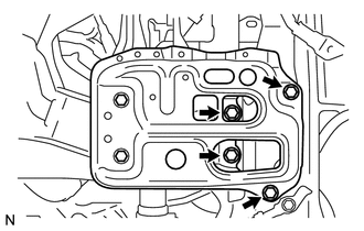
    2. Remove the 2 bolts and disconnect the radiator pipe from the battery carrier.

    3. A200723

      Remove the 4 bolts and battery carrier.

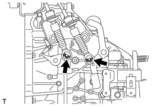
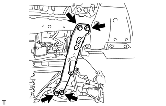
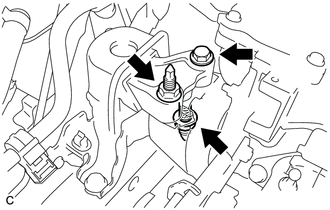
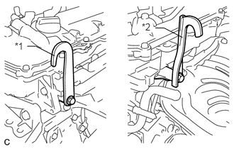
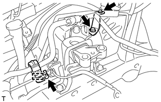
  29. DISCONNECT TRANSMISSION CONTROL CABLE ASSEMBLY (for Manual Transaxle)

    1. C201606

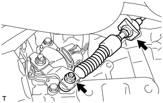
      Remove the 2 clips and disconnect the 2 cables from the transaxle.

    2. C201605

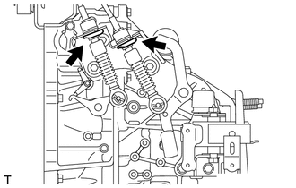
      Remove the 2 clips and disconnect the 2 cables from the control cable bracket.

    3. C197729

      Remove the nut and disconnect the control cable.

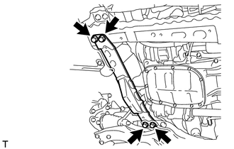
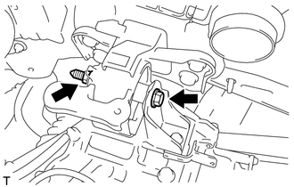
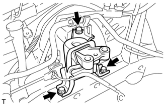
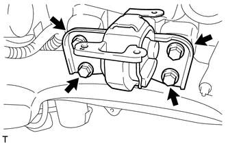
  30. DISCONNECT TRANSMISSION CONTROL CABLE ASSEMBLY (for CVT)

    1. C156645

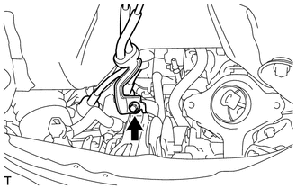
      Remove the nut and disconnect the control cable from the control shaft lever.

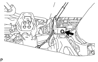
    2. Remove the clip and disconnect the transmission control cable from the control cable bracket.

    3. C201441

      Remove the bolt and separate the transmission control cable support.

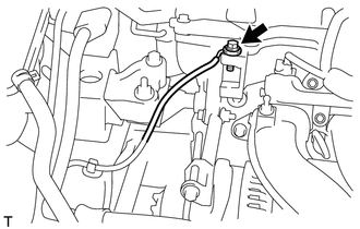
  31. DISCONNECT CLUTCH HOSE (for Manual Transaxle)

    1. A209972

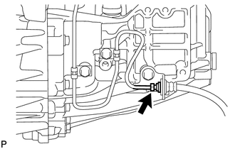
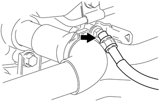
      Using a 10 mm union nut wrench, disconnect the clutch hose from the flexible hose tube.

    2. Remove the clip and disconnect the clutch hose.

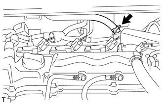
  32. DISCONNECT NO. 1 RADIATOR HOSE

    1. A209720

      for CVT:

      Disconnect the No. 1 breather plug from the clamp.

    2. A206127

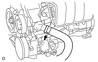
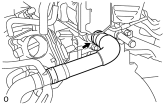
      Disconnect the radiator hose from the cylinder head.

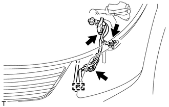
  33. DISCONNECT FUEL TUBE SUB-ASSEMBLY

    1. A150566

      Release the claw and remove the No. 1 fuel pipe clamp.

    2. A107343

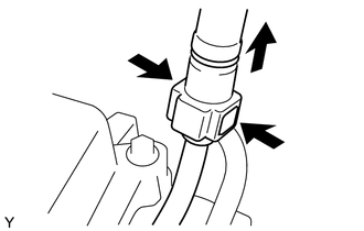
      Pinch the retainer as illustrated, and then pull the fuel tube connector off of the pipe.

      Note:
      • Remove any dirt and foreign matter from the fuel tube connector before performing this step.

      • Do not allow any scratches or foreign matter on the parts when disconnecting the fuel tube connector, as the connector contains the O-rings that seal the pipe.

      • Perform this work by hand. Do not use any tools.

      • Do not forcibly bend, kink or twist the nylon tube.

      • Protect the disconnected parts by covering them with vinyl bags after disconnecting the fuel tube.

      • If the fuel tube connector and pipe are stuck, push and pull to release them.

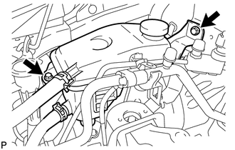
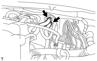
  34. DISCONNECT HEATER WATER HOSE

    1. A206121

      Disconnect the 2 heater water hoses.

  35. DISCONNECT WIRE HARNESS AND HOSE

    1. A350716E02

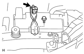
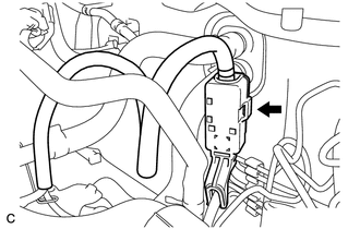
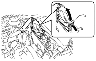
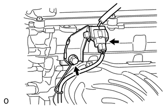
      Disconnect the clamp and ECM connector.

      1. Raise the lever while pushing the locks on the levers, and disconnect the ECM connector.

        Table 1. Text in Illustration

        *a

        Lock

        *b

        Push

        Note:

        After disconnecting the connector, make sure that dirt, water or other foreign matter does not contact the connecting parts of the connector.

    2. A200724

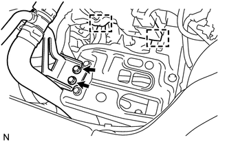
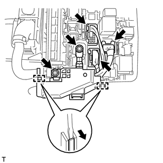
      Remove the 2 nuts from the engine room No. 1 relay block.

    3. Disconnect the 3 engine room No. 1 relay block connectors.

    4. Detach the 2 clamps and disconnect the wire harness.

    5. A200729

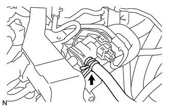
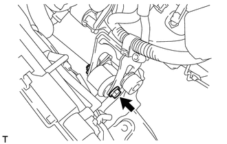
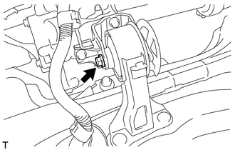
      Disconnect the battery current sensor connector.

    6. Remove the 2 bolts and disconnect the clamp and engine wire.

    7. A200730

      Remove the bolt and disconnect the engine wire.

    8. A200731

      Disconnect the connector tube hose

    9. A206118

      Disconnect the vacuum hose.

  36. SECURE STEERING WHEEL ASSEMBLY

  37. REMOVE COLUMN HOLE COVER SILENCER SHEET

  38. DISCONNECT NO. 2 STEERING INTERMEDIATE SHAFT ASSEMBLY

  39. DISCONNECT NO. 1 STEERING COLUMN HOLE COVER SUB-ASSEMBLY

  40. REMOVE FRONT FLOOR CENTER BRACE

  41. REMOVE FRONT EXHAUST PIPE ASSEMBLY

  42. REMOVE FRONT AXLE SHAFT NUT LH

  43. REMOVE FRONT AXLE SHAFT NUT RH

    Tip:

    Perform the same procedures described for the LH side.

  44. DISCONNECT FRONT STABILIZER LINK ASSEMBLY LH

  45. DISCONNECT FRONT STABILIZER LINK ASSEMBLY RH

    Tip:

    Perform the same procedures described for the LH side.

  46. REMOVE FRONT AXLE ASSEMBLY LH

    1. Remove the front axle assembly LH (Click here).

  47. REMOVE FRONT AXLE ASSEMBLY RH

    Tip:

    Perform the same procedures described for the LH side.

  48. REMOVE FRONT DRIVE SHAFT ASSEMBLY LH

  49. REMOVE FRONT DRIVE SHAFT ASSEMBLY RH

  50. REMOVE FRONT LOWER ENGINE MOUNTING BRACKET REINFORCEMENT

    1. A214302

      Remove the 2 bolt and front lower engine mounting bracket reinforcement.

  51. REMOVE DRIVE PLATE AND TORQUE CONVERTER SETTING BOLT (for CVT)

  52. REMOVE FRONT SUSPENSION MEMBER REINFORCEMENT LH

    1. A200733

      Remove the 4 bolts and front suspension member reinforcement LH.

  53. REMOVE FRONT SUSPENSION MEMBER REINFORCEMENT RH

    1. A200732

      Remove the 4 bolts and front suspension member reinforcement RH.

  54. REMOVE FRONT CROSSMEMBER SUB-ASSEMBLY

    1. A200734

      Remove the bolt and nut.

      Tip:

      While holding the nut in place, loosen the bolt.

    2. Remove the front engine mounting insulator from the front engine mounting bracket.

    3. A206114

      Remove the 4 bolts and front crossmember.

  55. REMOVE ENGINE ASSEMBLY WITH TRANSAXLE

    1. Set an engine lifter underneath the engine.

      Note:

      Place the engine on wooden blocks or equivalent so that the engine is level.

    2. A150570

      Remove the bolt and 2 nuts, and disconnect the engine mounting insulator RH.

    3. A214814

      Remove the bolt and nut, and disconnect the engine mounting insulator LH.

    4. A204889

      Remove the 6 bolts and front suspension member brace rear RH and LH.

    5. A202682

      Remove the 2 bolts and front suspension crossmember.

    6. Operate the engine lifter and slowly remove the engine from the vehicle.

      Note:
      • Make sure that the engine is clear of all wiring and hoses.

      • While lowering the engine from the vehicle, do not allow it to contact the vehicle.

  56. INSTALL ENGINE HANGER

    1. A206126

      Disconnect the air fuel ratio sensor connector and remove the bolt and air fuel ratio sensor bracket.

    2. U121282E01

      Install the 2 engine hangers with 2 bolts as shown in the illustration.

      43 N*m

      438 kgf*cm

      32 ft.*lbf

      Table 2. Text in Illustration

      *1

      No. 1 Engine Hanger

      *2

      No. 2 Engine Hanger

      Tip:

      No. 1 Engine Hanger

      12281-37021

      No. 2 Engine Hanger

      12282-37011

      Bolt

      91552-81050 or 90105-W0204

    3. Attach an engine sling device and hang the engine with a chain block.

  57. REMOVE FRONT SUSPENSION CROSSMEMBER SUB-ASSEMBLY

    1. A206115

      Remove the bolt and front suspension crossmember from the engine.

  58. REMOVE STARTER ASSEMBLY

  59. REMOVE FLYWHEEL HOUSING SIDE COVER

  60. REMOVE MANUAL TRANSAXLE ASSEMBLY

    1. Remove the manual transaxle assembly (Click here).

  61. REMOVE CONTINUOUSLY VARIABLE TRANSAXLE ASSEMBLY

    1. Remove the continuously variable transaxle assembly (Click here).

  62. REMOVE CLUTCH COVER ASSEMBLY (for Manual Transaxle)

  63. REMOVE CLUTCH DISC ASSEMBLY (for Manual Transaxle)

  64. REMOVE FLYWHEEL SUB-ASSEMBLY (for Manual Transaxle)

  65. REMOVE CLUTCH RELEASE WITH BEARING CYLINDER ASSEMBLY (for Manual Transaxle)

    1. Remove the clutch release with bearing cylinder assembly (Click here).

  66. REMOVE DRIVE PLATE AND RING GEAR SUB-ASSEMBLY (for CVT)

  67. REMOVE ENGINE WIRE

    1. Remove the engine wire from the engine.

  68. INSTALL ENGINE ON ENGINE STAND

    1. Install the engine onto an engine stand with the bolts.

    2. Remove the 2 bolts and 2 engine hangers.

  69. REMOVE FRONT ENGINE MOUNTING INSULATOR

    A206116
    Tip:

    Perform this procedure only when replacement of the engine mounting insulator is necessary.

    1. Remove the 2 bolts and front engine mounting insulator.

  70. REMOVE REAR ENGINE MOUNTING INSULATOR

    A206117
    Tip:

    Perform this procedure only when replacement of the engine mounting insulator is necessary.

    1. Remove the 2 bolts, 2 nuts and engine mounting insulator.

  71. REMOVE ENGINE MOUNTING INSULATOR SUB-ASSEMBLY RH

    A206123
    Tip:

    Perform this procedure only when replacement of the engine mounting insulator is necessary.

    1. Disconnect the cooler pipe clamp.

    2. Remove the 2 bolts, nut and 2 cooler pipe brackets.

    3. A206124

      Remove the 3 bolts and engine mounting insulator.

  72. REMOVE ENGINE MOUNTING INSULATOR SUB-ASSEMBLY LH

    A206125
    Tip:

    Perform this procedure only when replacement of the engine mounting insulator is necessary.

    1. Remove the 4 bolts and engine mounting insulator.