AIR CONDITIONING SYSTEM(for Automatic Air Conditioning System) Air Conditioning Compressor Magnetic Clutch Circuit
| DTC Code | DTC Name |
|---|---|
| Air Conditioning Compressor Magnetic Clutch Circuit |
DESCRIPTION
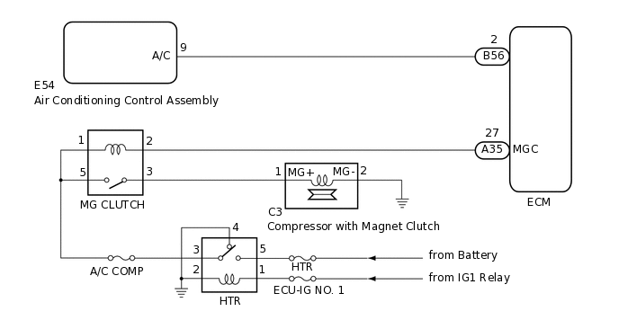
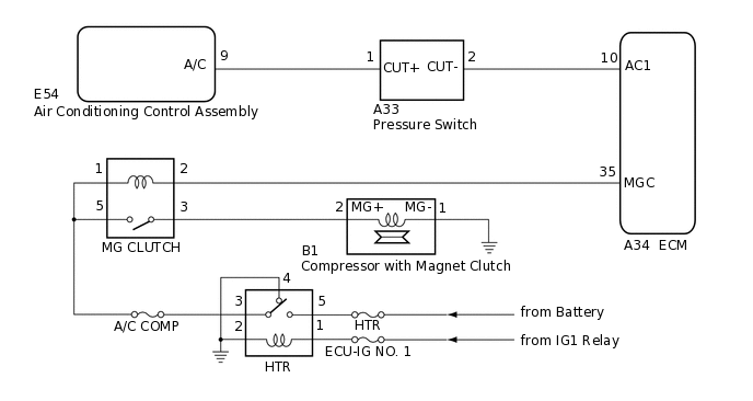
When the A/C switch of the air conditioning control assembly is turnd on, an A/C on signal is sent to the ECM. The ECM then turns on the MG CLUTCH relay to operate the compressor with magnet clutch.
WIRING DIAGRAM
for 1PP
for 1KR-FE
CAUTION / NOTICE / HINT
Inspect the fuses for circuits related to this system before performing the following inspection procedure.
PROCEDURE
CHECK HARNESS AND CONNECTOR (MG CLUTCH RELAY - POWER SOURCE)
Remove the MG CLUTCH relay.
Measure the voltage according to the value(s) in the table below.
Standard Voltage
Tester Connection
Condition
Specified Condition
Relay terminal 1 - Body ground
Ignition switch off
Below 1 V
Ignition switch ON
11 to 14 V
Relay terminal 5 - Body ground
Ignition switch off
Below 1 V
Ignition switch ON
11 to 14 V
Result
Proceed to
OK
NG
NG INSPECT HTR RELAYClick here
CONFIRM MODEL
Choose the model to be inspected.
Result
Result
Proceed to
for 1PP
A
for 1KR-FE
B
B INSPECT MG CLUTCH RELAYClick here
READ OUTPUT DTC (DTC P1543)
Clear the DTCs.
Powertrain > Engine > Clear DTCs
Check for DTCs.
Powertrain > Engine > Trouble Codes
Result
Result
Proceed to
DTC P1543 is output
A
DTC P1543 is not output
B
CHECK HARNESS AND CONNECTOR (ECM - AIR CONDITIONING CONTROL ASSEMBLY)
Disconnect the B56 ECM connector.
Disconnect the E54 air conditioning control assembly connector.
Measure the resistance according to the value(s) in the table below.
Standard Resistance
Tester Connection
Condition
Specified Condition
B56-2 - E54-9 (A/C)
Always
Below 1 Ω
B56-2 - Body ground
Always
10 kΩ or higher
Result
Proceed to
OK
NG
NG REPAIR OR REPLACE HARNESS OR CONNECTOR
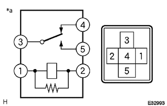
INSPECT MG CLUTCH RELAY
-
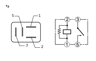
*a
Component without harness connected
(MG CLUTCH Relay)
Measure the resistance according to the value(s) in the table below.
Standard Resistance
Tester Connection
Condition
Specified Condition
3 - 5
Battery voltage not applied between terminals 1 and 2
10 kΩ or higher
Battery voltage applied between terminals 1 and 2
Below 1 Ω
Result
Proceed to
OK
NG
NG REPLACE MG CLUTCH RELAY
-
CHECK HARNESS AND CONNECTOR (MG CLUTCH RELAY - COMPRESSOR WITH MAGNET CLUTCH)
Disconnect the B1 compressor with magnet clutch connector.
Measure the resistance according to the value(s) in the table below.
Standard Resistance
Tester Connection
Condition
Specified Condition
Relay terminal 3 - B1-2 (MG+)
Always
Below 1 Ω
Relay terminal 3 - Body ground
Always
10 kΩ or higher
Result
Proceed to
OK
NG
NG REPAIR OR REPLACE HARNESS OR CONNECTOR
CHECK HARNESS AND CONNECTOR (MG CLUTCH RELAY - ECM)
Disconnect the A34 ECM connector.
Measure the resistance according to the value(s) in the table below.
Standard Resistance
Tester Connection
Condition
Specified Condition
Relay terminal 2 - A34-35 (MGC)
Always
Below 1 Ω
Relay terminal 2 - Body ground
Always
10 kΩ or higher
Result
Proceed to
OK
NG
NG REPAIR OR REPLACE HARNESS OR CONNECTOR
CHECK COMPRESSOR WITH MAGNET CLUTCH
-
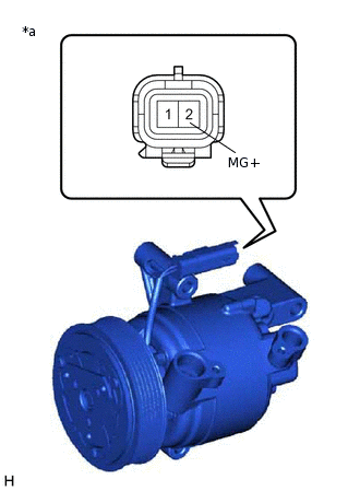
*a
Component without harness connected
(Compressor with Magnet Clutch)
Connect the compressor with magnet clutch connector.
When connector terminal 2 (MG+) is connected to a positive (+) battery terminal, check that the following occurs: 1) the magnetic clutch operating sound can be heard, and 2) the magnetic clutch hub and rotor lock.
OK
The magnetic clutch assembly operating sound can be heard, and the magnetic clutch hub and rotor lock.
Result
Proceed to
OK
NG
-
CHECK HARNESS AND CONNECTOR (PRESSURE SWITCH - ECM)
Disconnect the A33 pressure switch connector.
Measure the resistance according to the value(s) in the table below.
Standard Resistance
Tester Connection
Condition
Specified Condition
A34-10 (AC1) - A33-2 (CUT-)
Always
Below 1 Ω
A34-10 (AC1) - Body ground
Always
10 kΩ or higher
Result
Proceed to
OK
NG
NG REPAIR OR REPLACE HARNESS OR CONNECTOR
CHECK HARNESS AND CONNECTOR (PRESSURE SWITCH - AIR CONDITIONING CONTROL ASSEMBLY)
Disconnect the E54 air conditioning control assembly connector.
Measure the resistance according to the value(s) in the table below.
Standard Resistance
Tester Connection
Condition
Specified Condition
E54-9 (A/C) - A33-1 (CUT+)
Always
Below 1 Ω
E54-9 (A/C) - Body ground
Always
10 kΩ or higher
Result
Proceed to
OK
NG
NG REPAIR OR REPLACE HARNESS OR CONNECTOR
REPLACE PRESSURE SWITCH
Replace the pressure switch.
Tip:Since the pressure switch cannot be inspected while it is removed from the vehicle, replace the pressure switch with a new or known good one and check that the condition returns to normal.
OK
Malfunction disappears.
Result
Proceed to
OK
NG
OK END (PRESSURE SWITCH WAS DEFECTIVE)
INSPECT HTR RELAY
-
*a
Component without harness connected
(HTR Relay)
Remove the HTR relay.
Measure the resistance according to the value(s) in the table below.
Standard Resistance
Tester Connection
Condition
Specified Condition
3 - 5
Battery voltage not applied between terminals 1 and 2
10 kΩ or higher
Battery voltage applied between terminals 1 and 2
Below 1 Ω
3 - 4
Battery voltage not applied between terminals 1 and 2
Below 1 Ω
Battery voltage applied between terminals 1 and 2
10 kΩ or higher
Result
Proceed to
OK
NG
NG REPLACE HTR RELAY
-
CHECK HARNESS AND CONNECTOR (HTR RELAY - POWER SOURCE AND BODY GROUND)
Measure the voltage according to the value(s) in the table below.
Standard Voltage
Tester Connection
Condition
Specified Condition
Relay terminal 5 - Body ground
Always
11 to 14 V
Relay terminal 1 - Body ground
Ignition switch off
Below 1 V
Ignition switch ON
11 to 14 V
Measure the resistance according to the value(s) in the table below.
Standard Resistance
Tester Connection
Condition
Specified Condition
Relay terminal 2 - Body ground
Always
Below 1 Ω
Relay terminal 4 - Body ground
Always
Below 1 Ω
Result
Proceed to
OK
NG
NG REPAIR OR REPLACE HARNESS OR CONNECTOR
CHECK HARNESS AND CONNECTOR (MG CLUTCH RELAY - HTR RELAY)
Measure the resistance according to the value(s) in the table below.
Standard Resistance
Tester Connection
Condition
Specified Condition
MG CLUTCH relay terminal 1 - HTR relay terminal 3
Always
Below 1 Ω
MG CLUTCH relay terminal 1 - Body ground
Always
10 kΩ or higher
MG CLUTCH relay terminal 5 - HTR relay terminal 3
Always
Below 1 Ω
MG CLUTCH relay terminal 5 - Body ground
Always
10 kΩ or higher
Result
Proceed to
OK
NG
NG REPAIR OR REPLACE HARNESS OR CONNECTOR