OIL PUMP (for DPF) REMOVAL
Note
-
When replacing the injectors (including shuffling the injectors between the cylinders), common rail or cylinder head, it is necessary to replace the injection pipes with new ones.
-
When replacing the fuel supply pump, common rail, cylinder block, cylinder head, cylinder head gasket or timing gear case, it is necessary to replace the fuel inlet pipe with a new one.
-
After removing the injection pipes, clean them with a brush and compressed air.
-
DISCONNECT CABLE FROM NEGATIVE BATTERY TERMINAL
Note
When disconnecting the cable, some systems need to be initialized after the cable is reconnected Click here.
-
DRAIN ENGINE OIL
-
Remove the oil filler cap.
-
Remove the oil pan drain plug and gasket, and then drain the engine oil into a container.
-
Wipe the oil pan and drain plug.
-
Install a new gasket and the oil pan drain plug.
- Torque:
- 34 N*m { 347 kgf*cm, 25 ft.*lbf }
-
-
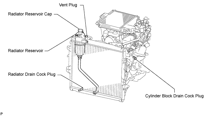
DRAIN ENGINE COOLANT
CAUTION:
Do not remove the radiator reservoir cap while the engine and radiator are still hot. Pressurized, hot engine coolant and steam may be released and cause serious burns.
-
Loosen the radiator drain cock plug.
Tech Tips
Collect the coolant in a container and dispose of it according to the regulations in your area.
-

Drain the coolant by removing the reservoir cap and, using a wrench, remove the vent plug.
-
Loosen the cylinder block drain cock plug.
-
-
REMOVE ENGINE ASSEMBLY
-
REMOVE NO. 1 TIMING BELT COVER
-
Remove the 6 bolts, 6 washers and timing belt cover.
-
-
REMOVE TIMING BELT
-
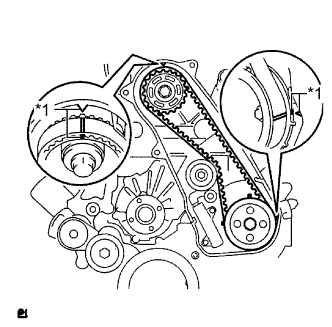
Text in Illustration *1 Timing Mark Turn the crankshaft clockwise and align the timing marks as shown in the illustration.
Tech Tips
If reusing the timing belt, place matchmarks on the timing belt so that it can be installed exactly as before.
-
Uniformly loosen and remove the 2 bolts and No. 1 timing belt tensioner.
-
Remove the timing belt.
Tech Tips
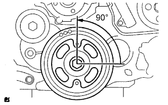
-
If turning the camshaft while the timing belt is removed, turn the crankshaft 90° counterclockwise as shown in the illustration.
-
When installing the timing belt, turn the camshaft to align the timing marks, and then turn the crankshaft clockwise to align the timing marks.
-
-
-
REMOVE NO. 1 TIMING BELT IDLER SUB-ASSEMBLY
Note
When inspecting the No. 1 timing belt idler, do not remove it unless absolutely necessary.
-
Using a 10 mm hexagon wrench, remove the bolt, No. 1 timing belt idler and washer.
-
-
REMOVE VISCOUS HEATER WITH MAGNET CLUTCH ASSEMBLY (w/ Viscous Heater)
-
REMOVE NO. 1 VISCOUS HEATER BRACKET SUB-ASSEMBLY (w/ Viscous Heater)
-
Remove the 4 bolts and No. 1 viscous heater bracket.
-
-
REMOVE NO. 2 IDLE PULLEY ASSEMBLY
-
Remove the bolt, pulley plate, No. 2 idle pulley and spacer.
-
-
REMOVE GENERATOR ASSEMBLY
-
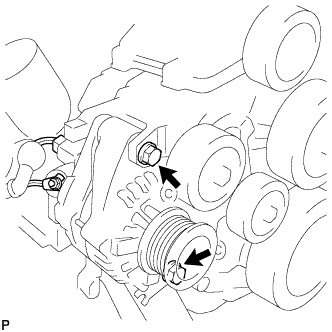
Remove the nut and generator wire.
-
Disconnect the generator connector.
-
Remove the 2 bolts and generator.
-
-
REMOVE GENERATOR BRACKET
-
Remove the bolt and generator bracket.
-
-
REMOVE V-RIBBED BELT TENSIONER ASSEMBLY
-
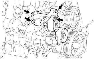
Remove the 4 bolts and V-ribbed belt tensioner.
-
-
REMOVE NO. 1 COMPRESSOR MOUNTING BRACKET (w/ Air Conditioning System)
-
Remove the 4 bolts and No. 1 compressor mounting bracket.
-
-
REMOVE ELECTRIC EGR CONTROL VALVE ASSEMBLY WITH NO. 2 EGR VALVE AND COOLER
-
REMOVE NO. 4 INJECTION PIPE SUB-ASSEMBLY
-
Remove the bolt, nut and 2 No. 2 injection pipe clamps.
-
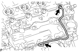
Using a 17 mm union nut wrench, loosen the union nuts and remove the No. 4 injection pipe.
-
-
REMOVE NO. 2 FUEL PIPE
-
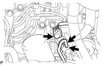
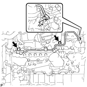
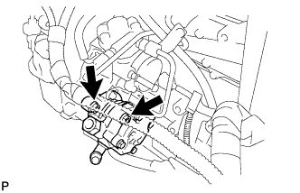
Disconnect the vacuum switching valve connector and 2 vacuum transmitting hoses.
-
Using a 6 mm hexagon wrench, remove the supply pump hollow screw and gasket.
Text in Illustration 
Bolt 
Supply Pump Hollow Screw 
Fuel Check Valve 
Union Bolt -
Remove the fuel check valve, union bolt and 2 gaskets.
-
Remove the 3 bolts and No. 2 fuel pipe.
-
-
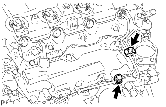
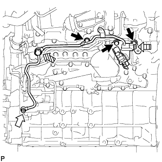
REMOVE NO. 3 NOZZLE LEAKAGE PIPE
-
Disconnect the 3 fuel hoses.
Text in Illustration Fuel Check Valve -
Remove the 2 bolts.
-
Remove the fuel check valve, gasket and No. 3 nozzle leakage pipe.
-
-
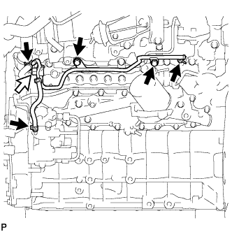
REMOVE NO. 2 NOZZLE LEAKAGE PIPE ASSEMBLY
-
Remove the 2 bolts.
Text in Illustration Union Bolt -
Remove the union bolt, gasket and No. 2 nozzle leakage pipe.
-
-
REMOVE NO. 2 CYLINDER HEAD COVER SUB-ASSEMBLY
-
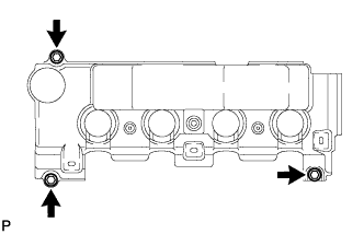
Remove the 3 bolts and No. 2 cylinder head cover.
-
-
REMOVE CYLINDER HEAD COVER SUB-ASSEMBLY
Note
If the cylinder head cover is removed, replace the 4 No. 3 cylinder head cover gaskets with new ones.
-
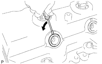
Using a small screwdriver, remove the nozzle holder seal by prying between the nozzle holder seal and the cutout part of the cylinder head cover.
-
Disconnect the ventilation hose.
-
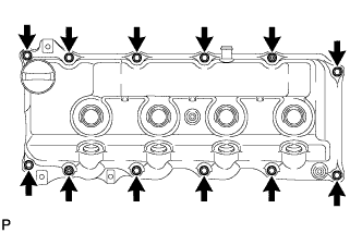
Remove the 10 bolts, 2 nuts, cylinder head cover and cylinder head cover gasket.
-
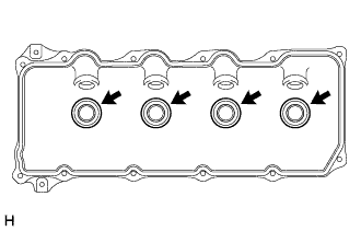
Remove the 4 No. 3 cylinder head cover gaskets from the cylinder head cover.
-
-
REMOVE CAMSHAFT TIMING PULLEY
-
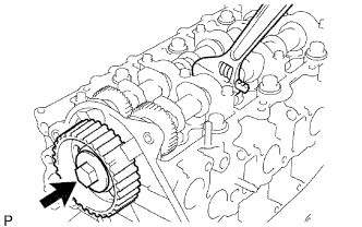
Remove the bolt of the camshaft timing pulley while holding the camshaft with a wrench.
Note
Make sure the timing belt is not installed when removing the bolt of the camshaft timing pulley.
-
Remove the camshaft timing pulley.
-
-
REMOVE NO. 2 TIMING BELT COVER
-
Remove the 4 bolts, nut and No. 2 timing belt cover.
-
-
REMOVE WATER PUMP ASSEMBLY
-
Remove the 5 bolts, 2 nuts, water pump and gasket.
-
-
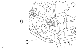
REMOVE VACUUM PUMP ASSEMBLY
-
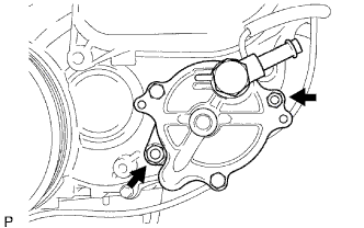
Remove the 2 nuts, vacuum pump and 2 O-rings.
-
-
REMOVE VANE PUMP ASSEMBLY
-
Remove the 2 nuts, vane pump and O-ring.
-
-
REMOVE CAMSHAFT POSITION SENSOR
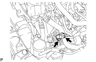
-
Disconnect the sensor connector.
-
Remove the bolt and sensor.
-
-
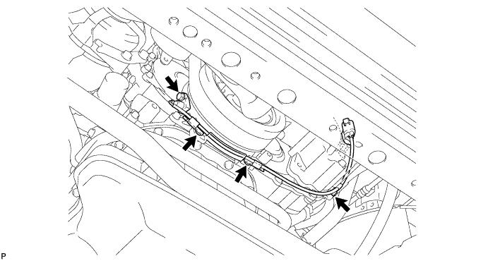
REMOVE CRANKSHAFT POSITION SENSOR
-
Disconnect the sensor connector.
-
Remove the 3 clips, bolt and sensor.
-
-
REMOVE PUMP DRIVE SHAFT PULLEY
-
Remove the 4 bolts, No. 2 camshaft timing pulley flange and pump drive shaft pulley.
-
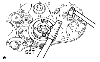
Using SST, hold the crankshaft pulley and remove the nut and O-ring.
- SST
- 09213-58014
- 09330-00021
-
-
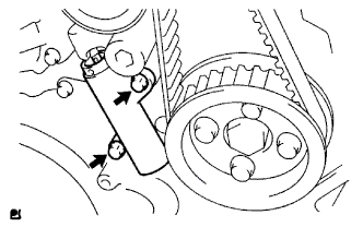
REMOVE CRANKSHAFT PULLEY
-
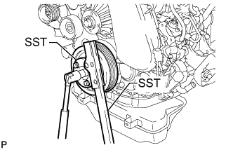
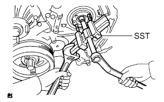
Using SST, hold the crankshaft pulley and loosen the pulley bolt.
- SST
- 09213-58014
- 09330-00021
-
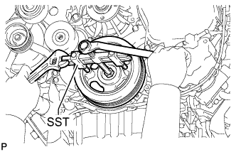
Using SST, remove the pulley bolt and crankshaft pulley.
- SST
- 09950-50013 ( 09951-05010, 09952-05010, 09953-05020, 09954-05021 )
Note
Apply oil or grease to the threads and tip of SST (center bolt) before using it.
-
-
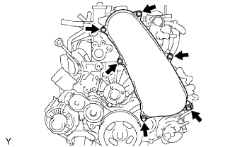
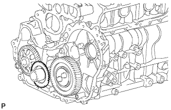
REMOVE TIMING GEAR COVER
Note
As the fuel supply pump is not installed, the injection gear is loose inside the timing gear case. Do not allow the injection gear to fall.
Tech Tips
To prevent the injection gear from falling, temporarily install the fuel supply pump.
-
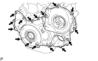
Remove the 14 bolts and 2 nuts.
-
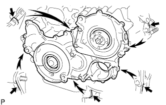
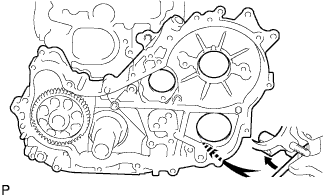
Pry the timing gear cover at the locations shown in the illustration and remove the timing gear cover.
Note
Be careful not to drop the injection gear.
-
Remove the O-ring from the timing gear case.
-
-
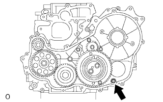
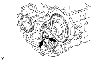
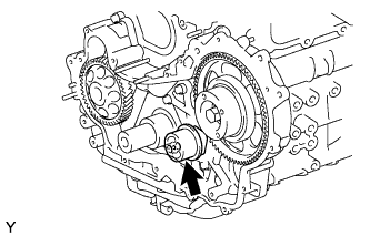
REMOVE INJECTION GEAR
-
Secure the No. 2 idle sub gear to the No. 1 idle gear with a service bolt.
- Torque:
- 8.0 N*m { 82 kgf*cm, 71 in.*lbf }
Note
If the bolt hole of the No. 2 idle sub gear is not aligned with the bolt hole of the No. 1 idle gear, rotate the crankshaft counterclockwise to align the bolt holes. Then install the service bolt.
-
Remove the injection gear.
-
-
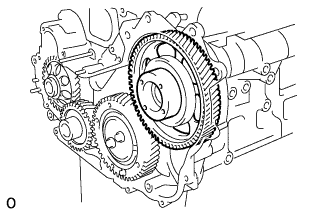
REMOVE NO. 1 CRANKSHAFT POSITION SENSOR PLATE
-
Remove the No. 1 crankshaft position sensor plate.
-
-
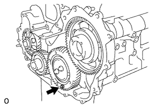
REMOVE CRANKSHAFT TIMING GEAR
-
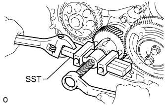
Using SST, remove the crankshaft timing gear.
- SST
- 09950-50013 ( 09951-05010, 09952-05010, 09953-05010, 09954-05021 )
-
-
REMOVE IDLE GEAR THRUST PLATE
-
Remove the 2 bolts and idle gear thrust plate.
-
-
REMOVE NO. 1 IDLE GEAR
-
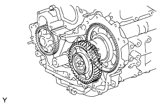
Remove the No. 1 idle gear together with the No. 2 idle sub gear.
-
-
REMOVE NO. 1 IDLE GEAR SHAFT
-
Remove the No. 1 idle gear shaft.
-
-
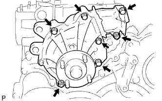
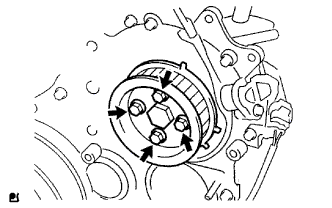
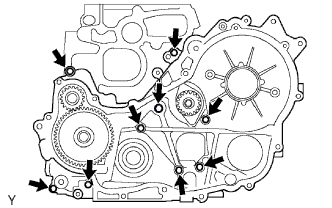
REMOVE FUEL SUPPLY PUMP ASSEMBLY
-
Disconnect the 2 fuel hoses.
-
Disconnect the fuel temperature sensor connector and suction control valve connector from the fuel supply pump.
-
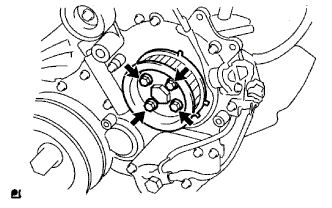
Remove the 4 bolts indicated by the arrows in the illustration.
-
Remove the No. 2 camshaft timing pulley flange and pump drive shaft pulley.
-
Remove the set nut and O-ring while holding the crankshaft pulley using SST.
- SST
- 09213-58014
- 09330-00021
-
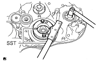
Loosen the 2 nuts.
-
Using SST, disconnect the fuel supply pump from the injection gear.
- SST
- 09950-50013 ( 09951-05010, 09952-05010, 09953-05020, 09954-05021 )
Note
Apply lubricant to the threads and tip of SST (center bolt) before using it.
-
Remove the 2 nuts and fuel supply pump.
Note
-
Do not hold or carry the fuel supply pump by the pipe.
-
The fuel supply pump must be kept horizontal.
-
-
Remove the O-ring.
-
-
REMOVE OIL PAN SUB-ASSEMBLY
-
Remove the 22 bolts and 2 nuts.
-
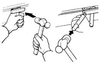
Insert the blade of an oil pan seal cutter between the oil pan and cylinder block, cut through the applied sealer and remove the oil pan.
Note
-
Do not use the oil pan seal cutter for the area between the oil pan and timing belt case, or for the area between the oil pan and rear oil seal retainer.
-
Be careful not to damage the oil pan flange.
-
-
-
REMOVE OIL STRAINER SUB-ASSEMBLY
-
Remove the 2 bolts, 2 nuts, oil strainer and gasket.
-
-
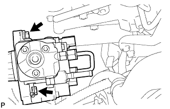
REMOVE TIMING GEAR CASE ASSEMBLY
-
Remove the union bolt and 8 bolts.
-
Pry the timing gear case at the location shown in the illustration and remove the gear case and gasket.
-
Remove the 2 O-rings.
-