POP UP HOOD SENSOR INSTALLATION

CAUTION / NOTICE / HINT
PROCEDURE
-
INSTALL PEDESTRIAN DETECTION CHAMBER ASSEMBLY
-
Align the center mark of the pedestrian detection chamber with the front bumper energy absorber positioning standard and set the parts into place as shown in the illustration.
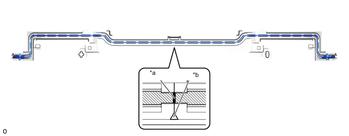
*a Center Mark of Pedestrian Detection Chamber *b Front Bumper Energy Absorber Positioning Standard -
Starting from the front bumper energy absorber positioning standard and working outward, install the pedestrian detection chamber to the pedestrian detection chamber connection areas of the front bumper energy absorber.
Note
-
Do not damage the pedestrian detection chamber connection area of the front bumper energy absorber.
-
If a pedestrian detection chamber connection area is damaged, replace the front bumper energy absorber with a new one.
-
Securely install the pedestrian detection chamber to every pedestrian detection chamber connection area of the front bumper energy absorber.
-
Install the pedestrian detection chamber so that it is free from twisting, deformation and excessive tightness, and it does not protrude from the front bumper energy absorber.
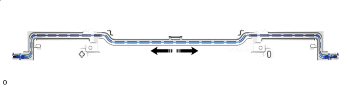

Install in this Direction - - -
-
Check that the center mark of the pedestrian detection chamber is within 10 mm of the front bumper energy absorber positioning standard.
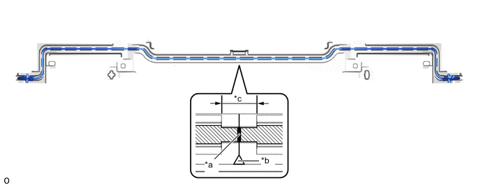
*a Center Mark of Pedestrian Detection Chamber *b Front Bumper Energy Absorber Positioning Standard *c 10 mm - - -
Attach the hook to install the front energy absorber mounting reinforcement RH to the RH side of the front bumper energy absorber.
-
Attach the hook to install the front energy absorber mounting reinforcement LH to the LH side of the front bumper energy absorber.
-
Install 2 new clips to the RH side of the front bumper energy absorber.
-
Install 2 new clips to the LH side of the front bumper energy absorber.
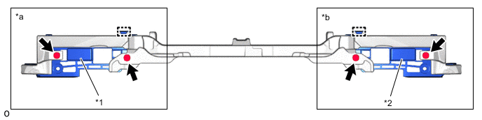
*1 Front Energy Absorber Mounting Reinforcement RH *2 Front Energy Absorber Mounting Reinforcement LH *a Front Bumper Energy Absorber RH Side *b Front Bumper Energy Absorber LH Side -
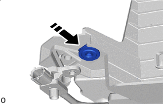
Install in this Direction Install a new nut.
Note
Do not reuse the nut.
Tech Tips
Use the same procedure for the opposite side.
-
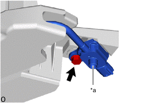
*a Breathing Filter Check that the breathing filter of the pedestrian protection sensor.
OK The breathing filter is not blocked by foreign matter or damaged. -
Install the pedestrian protection to the front energy absorber mounting reinforcement RH with a new bolt so that the breathing filter points downward.
- Torque:
- 6.0 N・m { 61 kgf・cm }
Note
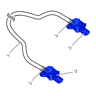
*1 Pedestrian Detection Chamber *2 Pedestrian Protection Sensor *3 Clip
-
When inspect the pedestrian detection chamber assembly, do not remove the pedestrian protection sensor.
-
Do not subject the pedestrian detection chamber assembly to any strong impact (such as dropping).
-
If the pedestrian protection sensor is subjected to any strong impact, replace the pedestrian detection chamber assembly with a new one.
-
Hold the pedestrian protection sensor so as not to damage the front energy absorber mounting reinforcement RH.
-
Do not pull only pedestrian protection sensor.
-
Do not pull only pedestrian detection chamber.
-
Do not reuse the bolt.
-
Do not open/close or move the tightening clips of the pedestrian detection chamber and pedestrian protection sensor.
Tech Tips
Use the same procedure for the opposite side.
-
Check that there is no looseness in the installation parts of the pedestrian detection chamber assembly.
-
Check that there is no blockage in the breathing filter due to foreign matter.
-
-
INSTALL FRONT BUMPER ENERGY ABSORBER SUB-ASSEMBLY
except Sports Package:
For Sports Package:
-
INSTALL FRONT BUMPER ASSEMBLY
except Sports Package:
For Sports Package:
-
CONNECT CABLE TO NEGATIVE BATTERY TERMINAL
Note
When disconnecting the cable, some systems need to be initialized after the cable is reconnected.
-
INSTALL LUGGAGE COMPARTMENT MAT SUB-ASSEMBLY
-
PERFORM DIAGNOSTIC SYSTEM CHECK
-
CHECK SRS WARNING LIGHT
-
PERFORM SYSTEM CALIBRATION