BRAKE PEDAL (w/ VSC) INSTALLATION
-
INSTALL BRAKE PEDAL SUPPORT SUB-ASSEMBLY
-
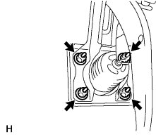
Install the support with the 4 nuts.
- Torque:
- 14 N*m { 145 kgf*cm, 10 ft.*lbf }
-
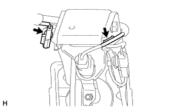
for 1KD-FTV and 2KD-FTV with Manual Transmission:
Attach the connector clamp and clamp to the brake pedal support sub-assembly.
-
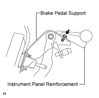
Install the bolt to the support.
- Torque:
- 18 N*m { 184 kgf*cm, 13 ft.*lbf }
-
-
CONNECT BRAKE MASTER CYLINDER PUSH ROD CLEVIS
-
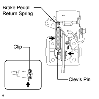
Apply a light coat of lithium soap base glycol grease to the clevis pin.
-
Connect the push rod clevis to the brake pedal.
-
Install the clevis pin and a new clip.
Note
The clip must be installed as shown in the illustration.
-
Install the return spring.
-
-
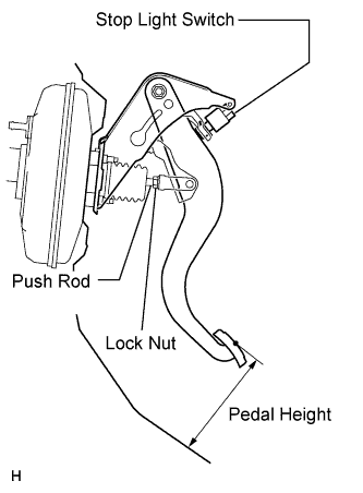
CHECK AND ADJUST BRAKE PEDAL HEIGHT
-
Check the pedal height.
Pedal height from dash panel Item Specified Condition LHD (M/T) 152.9 to 162.9 mm (6.020 to 6.413 in.) LHD (A/T) 154.1 to 164.1 mm (6.067 to 6.461 in.) RHD (M/T) 156.9 to 166.9 mm (6.177 to 6.571 in.) RHD (A/T) 158.1 to 168.1 mm (6.224 to 6.618 in.) -
Adjust the pedal height.
-
Disconnect the connector from the stop light switch.
-
Remove the switch.
-
Loosen the push rod clevis lock nut.
-
Adjust the pedal height by turning the push rod.
-
Tighten the lock nut.
- Torque:
- 26 N*m { 265 kgf*cm, 19 ft.*lbf }
-
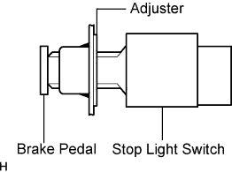
Insert the switch into the adjuster until it slightly touches the pedal.
Note
Do not depress the pedal.
-
Turn the switch a quarter turn clockwise.
- Torque:
- 1.5 N*m { 15 kgf*cm, 13 in.*lbf, or less }
Note
Do not depress the pedal.
-
Connect the connector to the switch.
-
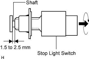
Check the switch clearance.
Stop light switch clearance 1.5 to 2.5 mm (0.0591 to 0.0984 in.)
-
-
-
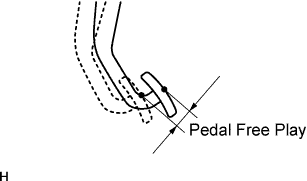
CHECK BRAKE PEDAL FREE PLAY
-
Stop the engine. Depress the pedal several times until there is no vacuum in the booster. Then release the pedal.
-
Depress the pedal until resistance is felt.
-
Check the pedal free play by measuring the distance between the position in the previous step and the pedal's released position.
Pedal free play 1.0 to 6.0 mm (0.0394 to 0.236 in.) If the free play is not as specified, check the switch clearance in the next step.
If the free play is as specified, proceed to the "check brake pedal reserve distance" procedure.
-
Check the switch clearance.
Stop light switch clearance 1.5 to 2.5 mm (0.0591 to 0.0984 in.) If the clearance is not as specified, adjust the clearance and recheck the pedal free play.
If the clearance is as specified, troubleshoot the brake system and proceed to the "check brake pedal reserve distance" procedure.
-
-
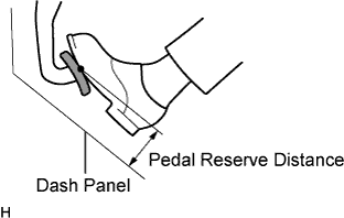
CHECK BRAKE PEDAL RESERVE DISTANCE
-
Release the parking brake lever. Start the engine.
-
Depress the pedal and check the pedal reserve distance.
-
Depress the pedal with a force of 490 N (50 kgf, 110 lbf).
-
Measure the distance between the pedal and dash panel shown in the illustration.
Pedal reserve distance Model Specified Condition for LHD 85.0 mm (3.347 in.) for RHD 89.0 mm (3.504 in.) If the distance is not as specified, troubleshoot the brake system.
-
-
-
INSTALL COMBINATION METER ASSEMBLY
-
Install the combination meter assembly Click here.
-
-
CONNECT CABLE TO NEGATIVE BATTERY TERMINAL
Note
When disconnecting the cable, some systems need to be initialized after the cable is reconnected Click here.
-
CHECK SRS WARNING LIGHT
-
w/ Airbag System:
Check the SRS warning light Click here.
-