HYBRID BATTERY SYSTEM, Diagnostic DTC:P0A95-123
| DTC Code | DTC Name |
|---|---|
| P0A95-123 | High Voltage Fuse |
DESCRIPTION
| DTC No. | INF Code | DTC Detection Condition | Trouble Area |
|---|---|---|---|
| P0A95 | 123 | Voltage between VA28 and GA2 terminals is below the standard despite the interlock switch being engaged (1 trip detection) |
|
WIRING DIAGRAM
Refer to the wiring diagram for DTC P0AE6-225 Click here.
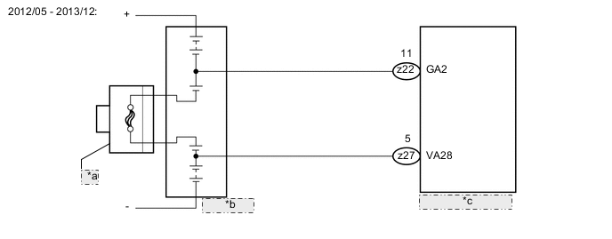
| *a | Service Plug Grip |
| *b | HV Battery |
| *c | Battery Smart Unit |
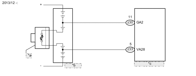
| *a | Service Plug Grip |
| *b | HV Battery |
| *c | Battery Smart Unit |
CAUTION / NOTICE / HINT
CAUTION:
-
Before inspecting the high-voltage system or disconnecting the low voltage connector of the inverter with converter assembly, take safety precautions such as wearing insulated gloves and removing the service plug grip to prevent electrical shocks. After removing the service plug grip, put it in your pocket to prevent other technicians from accidentally reconnecting it while you are working on the high-voltage system.
-
After removing the service plug grip, wait for at least 10 minutes before touching any of the high-voltage connectors or terminals. After waiting for 10 minutes, check the voltage at the terminals in the inspection point in the inverter with converter assembly. The voltage should be 0 V before beginning work Click here.
Tech Tips
Waiting for at least 10 minutes is required to discharge the high-voltage capacitor inside the inverter with converter assembly.
-
When disposing of an HV battery, make sure to return it through an authorized collection agent who is capable of handling it safely. If the HV battery is returned via the manufacturer specified route, it will be returned properly and in a safe manner by an authorized collection agent.
-
Before returning the HV battery, make sure to perform a recovery inspection Click here
-
Make a note of the output DTCs as some of them may be necessary for recovery inspection of the HV battery.
Note
After turning the power switch off, waiting time may be required before disconnecting the cable from the negative (-) auxiliary battery terminal. Therefore, make sure to read the disconnecting the cable from the negative (-) auxiliary battery terminal notices before proceeding with work Click here.
PROCEDURE
-
CHECK DTC OUTPUT (HYBRID CONTROL)
-
Connect the GTS to the DLC3.
-
Turn the power switch on (IG).
-
Enter the following menus: Powertrain / Hybrid Control / Trouble Codes.
-
Read output DTCs Click here.
Result Result Proceed to P0AFC-123 is not output. A P0AFC-123 is also output. B -
Turn the power switch off.
B 
GO TO DTC CHART (P0AFC-123) Click here
A 
-
-
CHECK HV BATTERY
CAUTION:
Be sure to wear insulated gloves.
-
Check that the service plug grip is not installed.
Note
After removing the service plug grip, do not turn the power switch on (READY), unless instructed by the repair manual because this may cause a malfunction.
-
Remove the No. 2 hybrid battery shield sub-assembly Click here.
-
Measure the resistance according to the value(s) in the table below.
Standard Resistance Tester Connection Condition Specified Condition k3-1 (+) - h3-1 (-) Power switch off 10 kΩ or higher -
Install the No. 2 hybrid battery shield sub-assembly.
NG 
CHECK HYBRID BATTERY JUNCTION BLOCK ASSEMBLY (SMRP, SMRB, SMRG) Click here
OK
-
-
CHECK INVERTER WITH CONVERTER ASSEMBLY
CAUTION:
Be sure to wear insulated gloves.
-
Check that the service plug grip is not installed.
Note
After removing the service plug grip, do not turn the power switch on (READY), unless instructed by the repair manual because this may cause a malfunction.
-
Remove the No. 2 hybrid battery shield sub-assembly Click here.
-

Measure the resistance according to the value(s) in the table below.
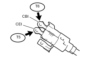
Standard Resistance Tester Connection Condition Specified Condition T6-1 (CBI) - T5-1 (CEI) Power switch off 10 kΩ or higher -
Install the No. 2 hybrid battery shield sub-assembly.
NG
CHECK HYBRID BATTERY JUNCTION BLOCK ASSEMBLY Click here
OK
-
-
INSPECT SERVICE PLUG GRIP
-
Disconnect the cable from the negative (-) auxiliary battery terminal.
-
Remove the service plug grip Click here.
-
Measure the resistance according to the value(s) in the table below.
Standard Resistance Tester Connection Condition Standard Resistance Service plug grip Always Below 1 Ω -
Reconnect the cable to the negative (-) auxiliary battery terminal.
OK
REPLACE HV BATTERY Click here
NG
REPLACE SERVICE PLUG GRIP Click here
-
-
CHECK HYBRID BATTERY JUNCTION BLOCK ASSEMBLY (SMRP, SMRB, SMRG)
CAUTION:
Be sure to wear insulated gloves.
-
Check that the service plug grip is not installed.
Note
After removing the service plug grip, do not turn the power switch on (READY), unless instructed by the repair manual because this may cause a malfunction.
-
Remove the No. 2 hybrid battery shield sub-assembly Click here.
-
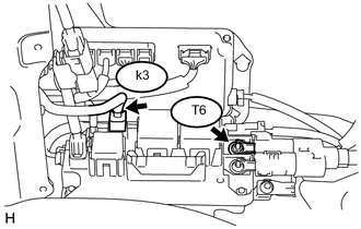
Measure the resistance according to the value(s) in the table below.
Standard Resistance (SMRB) Tester Connection Condition Specified Condition T6-1 (CBI) - k3-1 (+) Power switch off 10 kΩ or higher Tech Tips
If a system main relay is stuck closed, inspect the hybrid battery junction block assembly without removing it from the vehicle, in order to keep the relay closed.
-
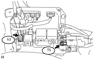
Measure the resistance according to the value(s) in the table below.
Standard Resistance (SMRG) Tester Connection Condition Specified Condition T5-1 (CEI) - h3-1 (-) Power switch off 10 kΩ or higher Tech Tips
-
If a system main relay is stuck closed, inspect the hybrid battery junction block assembly without removing it from the vehicle, in order to keep the relay closed.
-
If the resistance is between 28.5 and 31.5 Ω, it can be determined that SMRP is stuck closed.
-
-
Install the No. 2 hybrid battery shield sub-assembly.
NG
REPLACE HYBRID BATTERY JUNCTION BLOCK ASSEMBLY Click here
OK
-
-
CHECK HYBRID BATTERY JUNCTION BLOCK ASSEMBLY
CAUTION:
Be sure to wear insulated gloves.
-
Check that the service plug grip is not installed.
Note
After removing the service plug grip, do not turn the power switch on (READY), unless instructed by the repair manual because this may cause a malfunction.
-
Remove the No. 2 hybrid battery shield sub-assembly Click here.
-
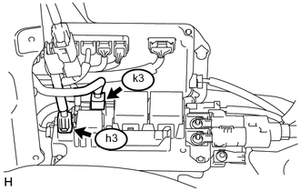
Disconnect the k3 and h3 hybrid battery junction block assembly connectors.
-
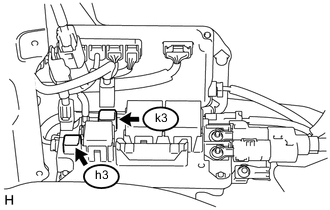
Measure the resistance according to the value(s) in the table below.
Standard Resistance Tester Connection Condition Specified Condition k3-1 (+) - h3-1 (-) Power switch off 10 kΩ or higher -
Reconnect the k3 and h3 hybrid battery junction block assembly connectors.
-
Install the No. 2 hybrid battery shield sub-assembly.
OK
REPLACE HV BATTERY Click here
NG
-
-
REPLACE HYBRID BATTERY JUNCTION BLOCK ASSEMBLY
NEXT
REPLACE SERVICE PLUG GRIP Click here
-
REPLACE HYBRID BATTERY JUNCTION BLOCK ASSEMBLY
NEXT
-
CHECK INVERTER WITH CONVERTER ASSEMBLY
CAUTION:
Be sure to wear insulated gloves.
-
Check that the service plug grip is not installed.
Note
After removing the service plug grip, do not turn the power switch on (READY), unless instructed by the repair manual because this may cause a malfunction.
-
Remove the No. 2 hybrid battery shield sub-assembly Click here.
-
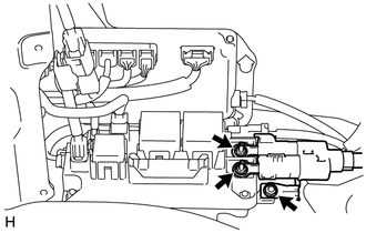
Disconnect the frame wire.
-
Measure the resistance according to the value(s) in the table below.
Standard Resistance Tester Connection Condition Specified Condition T6-1 (CBI) - T5-1 (CEI) Power switch off 10 kΩ or higher -
Connect the frame wire.
-
Install the No. 2 hybrid battery shield sub-assembly.
OK
REPLACE SERVICE PLUG GRIP Click here
NG
-
-
REPLACE INVERTER WITH CONVERTER ASSEMBLY
NEXT
REPLACE SERVICE PLUG GRIP Click here
-
CHECK HYBRID BATTERY JUNCTION BLOCK ASSEMBLY
CAUTION:
Be sure to wear insulated gloves.
-
Check that the service plug grip is not installed.
Note
After removing the service plug grip, do not turn the power switch on (READY), unless instructed by the repair manual because this may cause a malfunction.
-
Remove the No. 2 hybrid battery shield sub-assembly Click here.
-
Disconnect the frame wire.
-
Measure the resistance according to the value(s) in the table below.
Standard Resistance Tester Connection Condition Specified Condition T6-1 (CBI) - T5-1 (CEI) Power switch off 10 kΩ or higher -
Connect the frame wire.
-
Install the No. 2 hybrid battery shield sub-assembly.
NG
REPLACE HYBRID BATTERY JUNCTION BLOCK ASSEMBLY Click here
OK
-
-
REPLACE INVERTER WITH CONVERTER ASSEMBLY
NEXT
REPLACE SERVICE PLUG GRIP Click here
-
REPLACE HYBRID BATTERY JUNCTION BLOCK ASSEMBLY
NEXT
REPLACE SERVICE PLUG GRIP Click here