SHIFT LEVER ASSEMBLY INSTALLATION
PROCEDURE
-
INSTALL FLOOR SHIFT LEVER ASSEMBLY
-
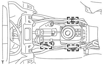
Attach the 2 claws to connect the shift control cable and select control cable to the shift lever assembly.
-
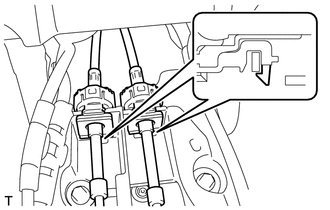
Connect the end of the shift control cable to the shift lever assembly and install the clip.
-
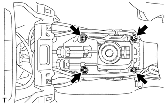
Install the shift lever assembly with the 4 bolts.
- Torque:
- 12 N*m { 122 kgf*cm, 9 ft.*lbf }
-
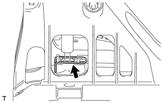
Attach the 3 wire harness clamps.
-
Release the lock of the cable length adjustment structure of the select cable.
-
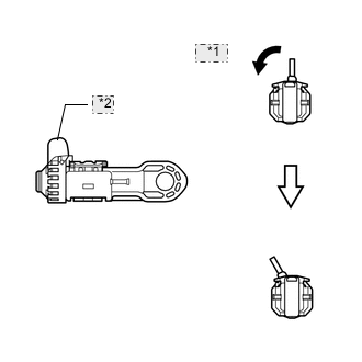
*1 Twist *2 Stopper Twist the stopper.
-
*1 Pull out *2 Lock Piece *3 Case Pull the lock piece outward from the case to release the lock.
-
-
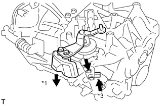
Pressing the shift and select lever shaft (*1) and pin (*2), push in pin (*3) and check that the shift and select lever shaft is secured at the 1st-2nd gear selected position (the shaft comes to a stop at the position 8 mm (0.315 in.) below the N position).
-
Connect the end of the select control cable to the shift lever assembly and install the clip.
Note
-
Make sure the lock piece of the select control cable is facing upward when the select control cable is connected.
-
Make sure the clip is inserted in the direction shown in the illustration.
-
-
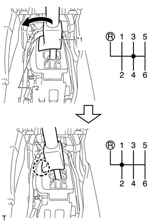
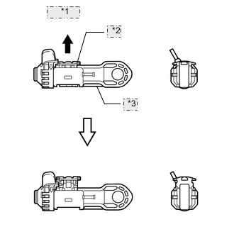
Text in Illustration *1 Slider *2 Inhibitor Wall Push the slider against the inhibitor wall.
Note
-
Do not pull up the slider.
-
When adjusting the cable, make sure that the shift lever is not in 1 or 2.
-
-
Lock the cable length adjustment structure of the select cable.
-
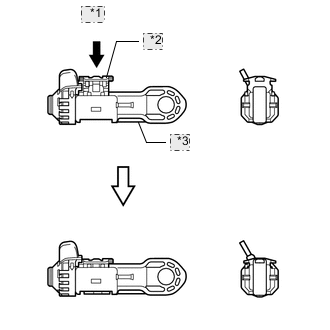
*1 Push *2 Lock Piece *3 Case Push the lock piece into the case with slider held against the inhibitor wall.
-
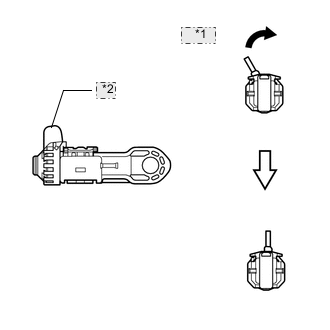
*1 Return *2 Stopper Return the stopper to prevent the lock from being released.
Note
-
Push in the lock piece completely.
-
Make sure that the cable length adjustment structure is locked securely.
-
-
-
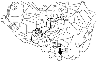
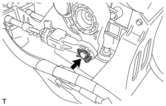
*1 Pull Release the pin that fixes the transmission outer lever.
-
Pull the pin toward the left front side of the vehicle.
-
-
-
INSTALL CONSOLE BOX ASSEMBLY