AUTOMATIC TRANSMISSION SYSTEM, Diagnostic DTC:P2757, P2758

| DTC Code | DTC Name |
|---|---|
| P2757 | Torque Converter Clutch Pressure Control Solenoid Performance (Shift Solenoid Valve SLU) |
| P2758 | Torque Converter Pressure Control Solenoid Circuit Stuck ON / Performance (SLU / DSU Solenoid) |
SYSTEM DESCRIPTION
The shift solenoid valve SLT is controlled by the duty ratio as determined in advance by the transmission control computer, based upon signals from the accelerator position sensor, input speed sensor NT and output speed sensor SP2. In this way, the line pressure is adjusted to match the throttle valve opening angle and engine output. The TCM uses the revolution signals from the input speed sensor NT and output speed sensor SP2 to detect clutch and other slipping.
| DTC No. | DTC Detection Condition
|
Trouble Area |
|---|---|---|
| P2757 |
|
|
| P2758 |
|
|
MONITOR DESCRIPTION
Torque converter lock-up is controlled by the TCM based on the input speed sensor NT, output speed sensor SP2, engine rpm, engine load, engine temperature, vehicle speed, transmission temperature, and gear selection. The TCM determines the lock-up status of the torque converter by comparing the engine rpm (NE) to the input turbine rpm (NT). The TCM calculates the actual transmission gear by comparing input turbine rpm (NT) to output shaft rpm (SP2). When conditions are appropriate, the TCM requests "lock-up" by applying control voltage to the shift solenoid SLU. When the SLU is turned on, it applies pressure to the lock-up relay valve and locks the torque converter clutch.
If the TCM detects no lock-up after lock-up has been requested or if it detects lock-up when it is not requested, the TCM interprets this as a fault in the shift solenoid valve SLU or lock-up system performance.
The TCM will turn on the MIL and store the DTC.
WIRING DIAGRAM
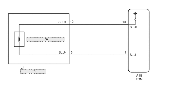
| *a | Shift Solenoid Valve SLU |
| *b | Transmission Wire |
CAUTION / NOTICE / HINT
Note
Perform the universal trip to clear permanent DTCs Click here.
-
ACTIVE TEST
Tech Tips
Using the GTS to perform Active Test allows relays, VSVs, actuators and other items to be operated without removing any parts. This non-intrusive functional inspection can be very useful because intermittent operation may be discovered before parts or wiring is disturbed. Performing Active Test early in troubleshooting is one way to save diagnostic time. Data List information can be displayed while performing Active Test.
-
Warm up the engine.
-
Turn the ignition switch off.
-
Connect the GTS to the DLC3.
-
Turn the ignition switch to ON.
-
Turn the GTS on.
-
Enter the following menus: Powertrain / ECT / Data List.
-
According to the display on the GTS, perform the "Active Test".
Item Test Details Diagnostic Note Activate the Lock Up [Test Details]
Control the shift solenoid SLU to set the automatic transmission to the lock-up condition.
[Vehicle Condition]
-
Throttle valve opening angle: Less than 35 %
-
Vehicle Speed: 50 km/h (30 mph) or more
Possible to check the SLU operation. Tech Tips
-
This test can be conducted when the vehicle speed is 50 km/h (30 mph) or more.
-
This test can be conducted with the 5th or 6th gear.
-
-
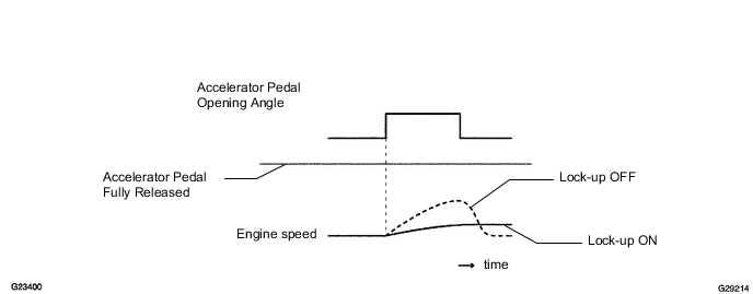
Lightly depress the accelerator pedal and check that the engine speed does not change abruptly.
Tech Tips
-
When changing the accelerator pedal opening angle while driving, if the engine speed does not change, lock-up is on.
-
Slowly release, but not fully, the accelerator pedal in order to decelerate. (Fully releasing the pedal will close the throttle valve and lock-up may be turned off automatically.)
-
-
PROCEDURE
-
CHECK OTHER DTCS OUTPUT
-
Connect the GTS to the DLC3.
-
Turn the ignition switch to ON and push the GTS main switch ON.
-
Read the DTCs using the GTS Click here.
Result Display (DTC output) Proceed to Only "P2757" or "P2758" is output A "P2757" or "P2758" and other DTCs B
B 
GO TO DTC CHART Click here
A 
-
-
INSPECT SHIFT SOLENOID VALVE SLU
-
Remove the shift solenoid valve SLU Click here.
-
Perform inspection of the shift solenoid valve SLU Click here.
NG
REPLACE SHIFT SOLENOID VALVE SLU Click here
OK
-
-
INSPECT TRANSMISSION VALVE BODY ASSEMBLY
-
Perform inspection of the transmission valve body assembly Click here.
OK There are no foreign objects on each valve.
NG
REPAIR OR REPLACE TRANSMISSION VALVE BODY ASSEMBLY Click here
OK
-
-
INSPECT TORQUE CONVERTER ASSEMBLY
-
Check the torque converter assembly Click here.
OK The torque converter clutch operates normally.
OK
REPAIR OR REPLACE AUTOMATIC TRANSMISSION ASSEMBLY Click here
NG
REPLACE TORQUE CONVERTER ASSEMBLY Click here
-