THEFT DETERRENT SYSTEM Starter Relay Circuit
DESCRIPTION
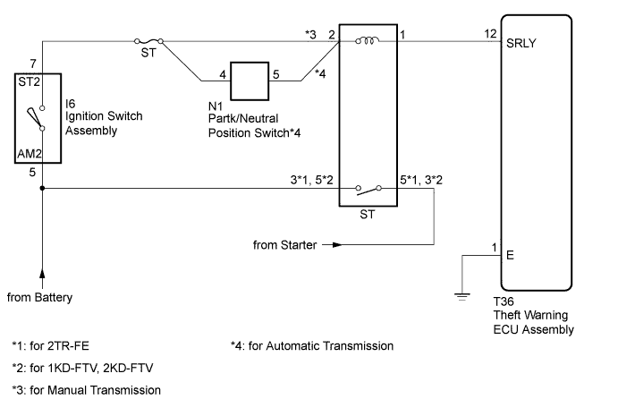
When the theft deterrent system operates, the theft warning ECU assembly deactivates the ST relay so that the starter cannot crank the engine.
WIRING DIAGRAM
INSPECTION PROCEDURE
Note
-
If the engine cranks but does not start, there is a problem with the SFI system*1 or ECD system*2. If this is the case, refer to SFI System*1 or ECD System*2 and perform troubleshooting.
-
*1: for 2TR-FE
-
*2: for 1KD-FTV, 2KD-FTV
-
Inspect the fuses for circuits related to this system before performing the following inspection procedure.
-
When replacing the theft warning ECU assembly, refer to the registration procedures Click here.
PROCEDURE
-
INSPECT ST RELAY
-
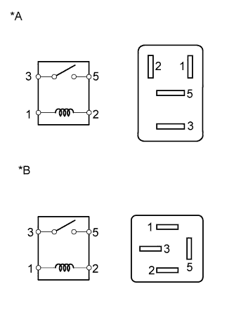
Text in Illustration *A for 2TR-FE *B for 1KD-FTV, 2KD-FTV Remove the ST relay from the engine room relay block and junction block assembly.
-
Measure the resistance according to the value(s) in the table below.
Standard Resistance Tester Connection Condition Specified Condition 3 - 5 Battery voltage is not applied to terminals 1 and 2 10 kΩ or higher Battery voltage is applied to terminals 1 and 2 Below 1 Ω
NG 
REPLACE ST RELAY
OK 
-
-
INSPECT IGNITION SWITCH ASSEMBLY
-
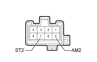
Remove the ignition switch assembly.
-
for 2TR-FE: Click here
-
for 1KD-FTV: Click here
-
for 2KD-FTV: Click here
-
-
Measure the resistance according to the value(s) in the table below.
Standard Resistance Tester Connection Switch Condition Specified Condition 5 (AM2) - 7 (ST2) Off, ACC, ON 10 kΩ or higher Start Below 1 Ω Result Result Proceed to OK A NG (for 2TR-FE) B NG (for 1KD-FTV) C NG (for 2KD-FTV) D
B
REPLACE IGNITION SWITCH ASSEMBLY Click here
C
REPLACE IGNITION SWITCH ASSEMBLY Click here
D
REPLACE IGNITION SWITCH ASSEMBLY Click here
A
-
-
CHECK VEHICLE TYPE
-
Check the vehicle type.
Result Result Proceed to for Automatic Transmission A for Manual Transmission B
B 
CHECK HARNESS AND CONNECTOR (ST RELAY - BATTERY) Click here
A
-
-
INSPECT PARK/NEUTRAL POSITION SWITCH ASSEMBLY
-
Remove the park/neutral position switch assembly.
-
for A340E: Click here
-
for A340F: Click here
-
for A343E: Click here
-
for A343F: Click here
-
for A750E: Click here
-
for A750F: Click here
-
-
Measure the resistance according to the value(s) in the table below.
Standard Resistance Tester Connection Switch Condition Specified Condition 4 - 5 Shift lever in P or N Below 1 Ω Shift lever not in P and N 10 kΩ or higher Tech Tips
If replacing the park/neutral position switch assembly, refer to the procedures above.
NG
REPLACE PARK/NEUTRAL POSITION SWITCH ASSEMBLY Click here
OK
-
-
CHECK HARNESS AND CONNECTOR (ST RELAY - BATTERY)
-
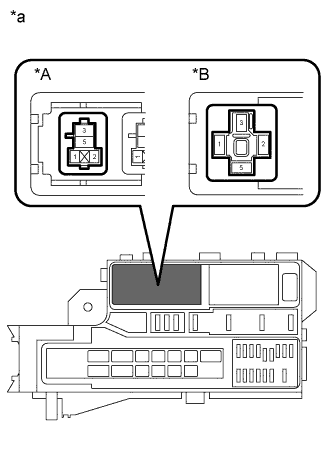
Text in Illustration *A for 2TR-FE *B for 1KD-FTV, 2KD-FTV *a Front view of wire harness connector
(to ST Relay)
Remove the ST relay from the engine room relay block.
-
Measure the voltage according to the value(s) in the table below.
Standard Voltage for 2TR-FE Tester Connection Condition Specified Condition Relay block ST relay terminal 3 - Body ground Always 11 to 14 V for 1KD-FTV, 2KD-FTV Tester Connection Condition Specified Condition Relay block ST relay terminal 5 - Body ground Always 11 to 14 V
NG
REPAIR OR REPLACE HARNESS OR CONNECTOR
OK
-
-
CHECK HARNESS AND CONNECTOR (THEFT WARNING ECU - BATTERY AND BODY GROUND)
-
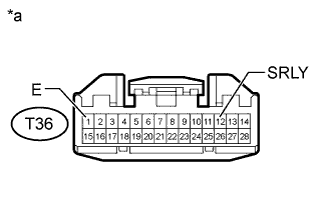
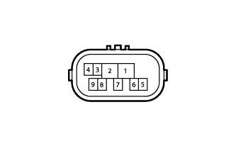
Text in Illustration *a Front view of wire harness connector
(to Theft Warning ECU Assembly)
Disconnect the T36 theft warning ECU assembly connector.
-
Measure the resistance according to the value(s) in the table below.
Standard Resistance Tester Connection Condition Specified Condition T36-1 (E) - Body ground Always Below 1 Ω -
Measure the voltage according to the value(s) in the table below.
Standard Voltage Tester Connection Switch Condition Specified Condition T36-12 (SRLY) - Body ground Ignition switch off Below 1 V Ignition switch ON 11 to 14 V
NG
REPAIR OR REPLACE HARNESS OR CONNECTOR
OK 
REPLACE THEFT WARNING ECU ASSEMBLY
-