AIR CONDITIONING SYSTEM PTC Heater Circuit
| DTC Code | DTC Name |
|---|---|
| PTC Heater Circuit |
DESCRIPTION
PTC heater relays are closed in accordance with signals from the air conditioning amplifier assembly and power is supplied to the quick heater assembly installed on the radiator heater unit.
WIRING DIAGRAM
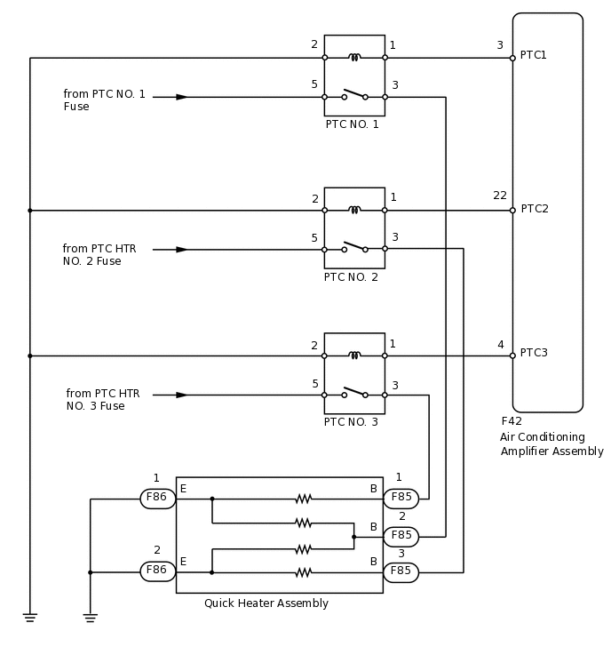
PROCEDURE
INSPECT PTC HEATER RELAY (PTC NO.1, PTC NO.2, PTC NO.3)
-
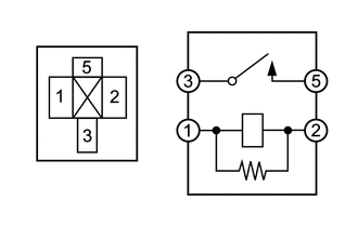
Remove the PTC NO.1, PTC NO.2 and PTC NO.3 relays from the engine room No. 2 relay block.
Measure the resistance according to the value(s) in the table below.
Standard Resistance
Tester Connection
Condition
Specified Condition
3 - 5
Battery voltage is not applied to terminals 1 and 2
10 kΩ or higher
Battery voltage is applied to terminals 1 and 2
Below 1 Ω
Result
Proceed to
OK
NG
NG REPLACE PTC HEATER RELAY (PTC NO.1, PTC NO.2, PTC NO.3)
-
CHECK AIR CONDITIONING AMPLIFIER ASSEMBLY
-
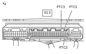
*a
Component with harness connected
(Air Conditioning Amplifier Assembly)
Remove the air conditioning amplifier assembly with its connectors still connected.
Measure the voltage according to the value(s) in the table below.
Standard Voltage
Tester Connection
Condition
Specified Condition
G13-3 (PTC1) - Body ground
Engine running (1250 rpm or more)
Temperature setting MAX HOT
Outside temperature 10°C (50°F) or less
Engine coolant temperature 79°C (174°F) or less
Headlight dimmer switch off
Blower switch off
Below 1 V*
G13-22 (PTC2) - Body ground
Engine running (1250 rpm or more)
Temperature setting MAX HOT
Outside temperature 10°C (50°F) or less
Engine coolant temperature 76°C (169°F) or less
Headlight dimmer switch off
Blower switch off
G13-4 (PTC3) - Body ground
Engine running (1250 rpm or more)
Temperature setting MAX HOT
Outside temperature 10°C (50°F) or less
Engine coolant temperature 73°C (163°F) or less
Headlight dimmer switch off
Blower switch off
G13-3 (PTC1) - Body ground
Engine running (1250 rpm or more)
Temperature setting MAX HOT
Outside temperature 10°C (50°F) or less
Engine coolant temperature 79°C (174°F) or less
Headlight dimmer switch off
Blower switch on
11 to 14 V*
G13-22 (PTC2) - Body ground
Engine running (1250 rpm or more)
Temperature setting MAX HOT
Outside temperature 10°C (50°F) or less
Engine coolant temperature 76°C (169°F) or less
Headlight dimmer switch off
Blower switch on
G13-4 (PTC3) - Body ground
Engine running (1250 rpm or more)
Temperature setting MAX HOT
Outside temperature 10°C (50°F) or less
Engine coolant temperature 73°C (163°F) or less
Headlight dimmer switch off
Blower switch on
Tip:*: After the measurement conditions are met, wait 30 seconds before performing measurements.
Result
Proceed to
OK
NG
-
CHECK HARNESS AND CONNECTOR (ENGINE ROOM NO. 2 RELAY BLOCK - AIR CONDITIONING AMPLIFIER)
Remove the PTC heater relays from the engine room No. 2 relay block.
Disconnect the G13 amplifier connector.
Measure the resistance according to the value(s) in the table below.
Standard Resistance
Tester Connection
Condition
Specified Condition
PTC NO.1 relay terminal 1 - G13-3 (PTC1)
Always
Below 1 Ω
PTC NO.2 relay terminal 1 - G13-22 (PTC2)
PTC NO.3 relay terminal 1 - G13-4 (PTC3)
PTC NO.1 relay terminal 1 - Body ground
Always
Below 1 Ω
PTC NO.2 relay terminal 1 - Body ground
PTC NO.3 relay terminal 1 - Body ground
Result
Proceed to
OK
NG
NG REPAIR OR REPLACE HARNESS OR CONNECTOR
CHECK HARNESS AND CONNECTOR (ENGINE ROOM NO. 2 RELAY BLOCK - QUICK HEATER)
Remove the PTC heater relays from the engine room No. 2 relay block.
Disconnect the G105 heater connector.
Measure the resistance according to the value(s) in the table below.
Standard Resistance
Tester Connection
Condition
Specified Condition
PTC NO.1 relay terminal 3 - G105-2 (B)
Always
Below 1 Ω
PTC NO.2 relay terminal 3 - G105-3 (B)
PTC NO.3 relay terminal 3 - G105-1 (B)
PTC NO.1 relay terminal 3 - Body ground
Always
Below 1 Ω
PTC NO.2 relay terminal 3 - Body ground
PTC NO.3 relay terminal 3 - Body ground
Result
Proceed to
OK
NG
NG REPAIR OR REPLACE HARNESS OR CONNECTOR
CHECK HARNESS AND CONNECTOR (ENGINE ROOM NO. 2 RELAY BLOCK - BATTERY AND BODY GROUND)
-
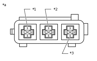
*1
PTC NO.1 Relay
*2
PTC NO.2 Relay
*3
PTC NO.3 Relay
*a
Component without relay installed
(Engine Room No. 2 Relay Block)
Remove the PTC heater relays from the engine room No. 2 relay block.
Measure the voltage according to the value(s) in the table below.
Standard Voltage
Tester Connection
Condition
Specified Condition
PTC NO.1 relay terminal 5 - Body ground
Always
11 to 14 V
PTC NO.2 relay terminal 5 - Body ground
PTC NO.3 relay terminal 5 - Body ground
Measure the resistance according to the value(s) in the table below.
Standard Resistance
Tester Connection
Condition
Specified Condition
PTC NO.1 relay terminal 2 - Body ground
Always
Below 1 Ω
PTC NO.2 relay terminal 2 - Body ground
PTC NO.3 relay terminal 2 - Body ground
Result
Proceed to
OK
NG
NG REPAIR OR REPLACE HARNESS OR CONNECTOR
-
INSPECT QUICK HEATER ASSEMBLY
Remove the quick heater assembly.
Measure the resistance according to the value(s) in the table below.
Standard Resistance
Tester Connection
Condition
Specified Condition
A-1 (B) - B-1 (E)
Always
Below 1 Ω
A-2 (B) - B-1 (E)
A-2 (B) - C-1 (E)
A-3 (B) - C-1 (E)
Result
Proceed to
OK
NG
CHECK HARNESS AND CONNECTOR (QUICK HEATER - BODY GROUND)
-
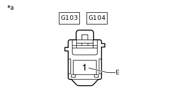
*a
Front view of wire harness connector
(to Quick Heater Assembly)
Disconnect the G103 and G104 quick heater connectors.
Measure the resistance according to the value(s) in the table below.
Standard Resistance
Tester Connection
Condition
Specified Condition
G103-1 (E) - Body ground
Always
Below 1 Ω
G104-1 (E) - Body ground
Result
Proceed to
OK
NG
NG REPAIR OR REPLACE HARNESS OR CONNECTOR
-