SFI SYSTEM, Diagnostic DTC:P0851, P0852
| DTC Code | DTC Name |
|---|---|
| P0851 | Park / Neutral Switch Input Circuit Low |
| P0852 | Park / Neutral Switch Input Circuit High |
DESCRIPTION
| DTC No. | DTC Detection Condition | Trouble Area |
|---|---|---|
| P0851 |
for Manual Transmission
for Automatic Transmission |
for Manual Transmission
for Automatic Transmission |
| P0852 |
for Manual Transmission
for Automatic Transmission |
for Manual Transmission
for Automatic Transmission |
MONITOR DESCRIPTION
-
The ECM detects the shift change status from the neutral position switch signal, and detects the current selected gear from the engine speed and vehicle speed. If the neutral position switch signal and the shift change status cannot be coordinated, the ECM interprets this as a malfunction, illuminates the MIL, and stores the DTC.
for Manual Transmission
-
If the ECM cannot coordinate the N, P or neutral information from the park/neutral position switch signal with the shift information sent from the TCM through CAN communication, then the ECM interprets this as a malfunction, illuminates the MIL, and stores the DTC.
for Automatic Transmission
CONFIRMATION DRIVING PATTERN
-
-
-
Connect the GTS to the DLC3.
-
Turn the ignition switch to ON and turn the GTS on.
-
Clear DTCs (even if no DTCs are stored, perform the clear DTC operation) Click here.
-
Turn the ignition switch off and wait for at least 30 seconds.
-
Turn the ignition switch to ON and turn the GTS on.
-
Start the engine and warm it up until the engine coolant temperature reaches 75°C (167°F) or higher.
-
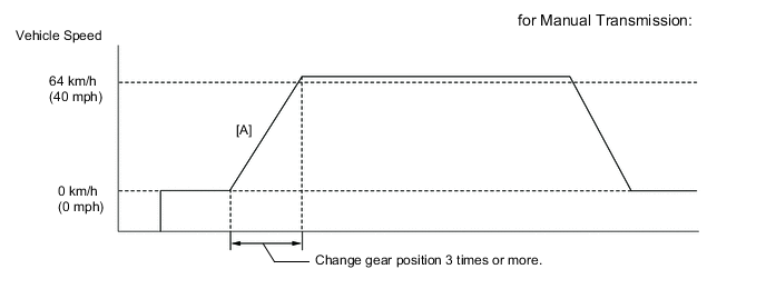
Change gear position 3 times or more during Accelerating vehicle to 64 km/h (40 mph) [A]. (for Manual Transmission)
CAUTION:
When performing the confirmation driving pattern, obey all speed limits and traffic laws.
-
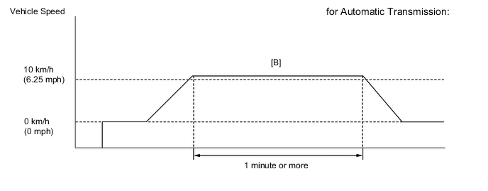
Drive the vehicle at 10 km/h (6.25 mph) or more for 1 minute or more [B]. (for Automatic Transmission)
CAUTION:
When performing the confirmation driving pattern, obey all speed limits and traffic laws.
-
Enter the following menus: Powertrain / Engine / Trouble Codes.
-
Read pending DTCs.
Tech Tips
-
If a pending DTC is output, the system is malfunctioning.
-
If a pending DTC is not output, perform the following procedure.
-
-
Enter the following menus: Powertrain / Engine / Utility / All Readiness.
-
Input the DTC: P0851 or P0852.
-
Check the DTC judgment result.
GTS Display Description NORMAL
-
DTC judgment completed
-
System normal
ABNORMAL
-
DTC judgment completed
-
System abnormal
INCOMPLETE
-
DTC judgment not completed
-
Perform driving pattern after confirming DTC enabling conditions
N/A
-
Unable to perform DTC judgment
-
Number of DTCs which do not fulfill DTC preconditions has reached ECU memory limit
Tech Tips
-
If the judgment result shows NORMAL, the system is normal.
-
If the judgment result shows ABNORMAL, the system has a malfunction.
-
-
If the test result is INCOMPLETE or N/A and no DTC is output, perform a universal trip and check for permanent DTCs Click here.
Tech Tips
-
If a permanent DTC is output, the system is malfunctioning.
-
If no permanent DTC is output, the system is normal.
-
WIRING DIAGRAM
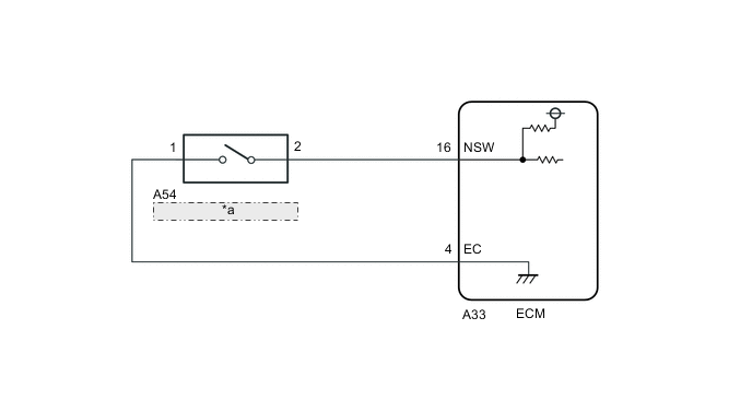
| *a | Neutral Position Switch |
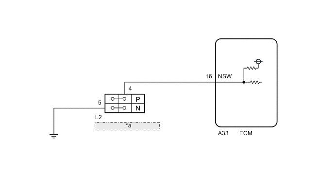
| *a | Park/Neutral Position Switch Assembly |
CAUTION / NOTICE / HINT
Note
Inspect the fuses for circuits related to this system before performing the following inspection procedure.
Tech Tips
-
Read freeze frame data using the GTS. The ECM records vehicle and driving condition information as freeze frame data the moment a DTC is stored. When troubleshooting, freeze frame data can help determine if the vehicle was moving or stationary, if the engine was warmed up or not, if the air fuel ratio was lean or rich, and other data from the time the malfunction occurred.
-
Stop light switch assembly conditions can be checked using the GTS.
-
Connect the GTS to the DLC3.
-
Turn the ignition switch to ON.
-
Turn the GTS on.
-
Enter the following menus: Powertrain / Engine / Data List / Stop Light Switch and ST1.
-
Check the Data List indication when the brake pedal is depressed and released.
Brake Pedal Operation Stop Light Switch ST1 Depressed ON ON Released OFF OFF
PROCEDURE
-
CHECK VEHICLE TYPE
-
Confirm the transmission.
Result Result Proceed to for Manual Transmission A for Automatic Transmission B
B 
INSPECT TERMINAL VOLTAGE (POWER SOURCE OF PARK/NEUTRAL POSITION SWITCH ASSEMBLY) Click here
A 
-
-
INSPECT TERMINAL VOLTAGE (POWER SOURCE OF NEUTRAL POSITION SWITCH)
-
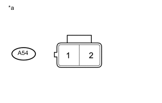
Text in Illustration *a Front view of wire harness connector
(to Neutral Position Switch)
Disconnect the neutral position switch connector.
-
Measure the voltage according to the value(s) in the table below.
Standard Voltage Tester Connection Condition Specified Condition A54-1 - A54-2 Ignition switch ON 11 to 14 V
NG
CHECK HARNESS AND CONNECTOR (NEUTRAL POSITION SWITCH - ECM) Click here
OK
-
-
INSPECT NEUTRAL POSITION SWITCH
-
Inspect the neutral position switch Click here.
OK 
CHECK FOR INTERMITTENT PROBLEMS Click here
NG
REPLACE NEUTRAL POSITION SWITCH Click here
-
-
CHECK HARNESS AND CONNECTOR (NEUTRAL POSITION SWITCH - ECM)
-
Disconnect the ECM connector.
-
Disconnect the neutral position switch connector.
-
Measure the resistance according to the value(s) in the table below.
Standard Resistance (Check for open) Tester Connection Condition Specified Condition A33-16 (NSW) - A54-2 Always Below 1 Ω A33-4 (EC) - A54-1 Always Below 1 Ω Standard Resistance (Check for short) Tester Connection Condition Specified Condition A33-16 (NSW) or A54-2 - Body ground Always 10 kΩ or higher A33-4 (EC) or A54-1 - Body ground Always 10 kΩ or higher
OK
REPLACE ECM Click here
NG
REPAIR OR REPLACE HARNESS OR CONNECTOR
-
-
INSPECT TERMINAL VOLTAGE (POWER SOURCE OF PARK/NEUTRAL POSITION SWITCH ASSEMBLY)
-
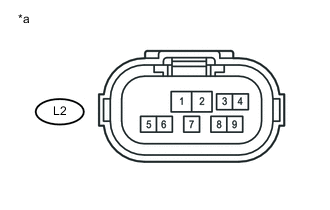
Text in Illustration *a Front view of wire harness connector
(to Park/Neutral Position Switch Assembly)
Disconnect the park/neutral position switch assembly connector.
-
Measure the voltage according to the value(s) in the table below.
Standard Voltage Tester Connection Condition Specified Condition L2-4 - L2-5 Ignition switch ON 11 to 14 V
NG
CHECK HARNESS AND CONNECTOR (PARK/NEUTRAL POSITION SWITCH ASSEMBLY - ECM - BODY GROUND) Click here
OK
-
-
INSPECT PARK/NEUTRAL POSITION SWITCH ASSEMBLY
-
Inspect the park/neutral position switch assembly Click here.
OK
CHECK FOR INTERMITTENT PROBLEMS Click here
NG
REPLACE PARK/NEUTRAL POSITION SWITCH ASSEMBLY Click here
-
-
CHECK HARNESS AND CONNECTOR (PARK/NEUTRAL POSITION SWITCH ASSEMBLY - ECM - BODY GROUND)
-
Disconnect the ECM connector.
-
Disconnect the park/neutral position switch assembly connector.
-
Measure the resistance according to the value(s) in the table below.
Standard Resistance (Check for open) Tester Connection Condition Specified Condition A33-16 (NSW) - L2-4 Always Below 1 Ω L2-5 - Body ground Always Below 1 Ω Standard Resistance (Check for short) Tester Connection Condition Specified Condition A33-16 (NSW) or L2-4 - Body ground Always 10 kΩ or higher
OK
REPLACE ECM Click here
NG
REPAIR OR REPLACE HARNESS OR CONNECTOR
-