VACUUM PUMP(When Using the Engine Support Bridge for AD Series Engine) INSTALLATION
PROCEDURE
INSTALL VACUUM PUMP ASSEMBLY
-
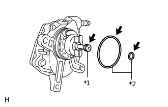
*1
Oil Pipe
*2
O-Ring
Apply engine oil to the oil pipe at the tip of the vacuum pump.
Coat 2 new O-rings with engine oil, and install them to the vacuum pump.
-
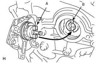
Install the vacuum pump so that the coupling teeth of the vacuum pump labeled A and the groove of the camshaft labeled B can engage.
-
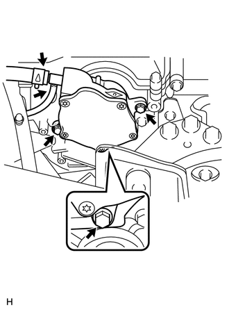
Install 3 new flange bolts.
21 N*m
214 kgf*cm
15 ft.*lbf
Connect the 2 vacuum hoses, and slide the clamp to secure it.
-
INSTALL ENGINE MOUNTING INSULATOR SUB-ASSEMBLY RH
-
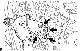
Connect the engine mounting insulator sub-assembly RH with the 2 bolts and 2 nuts.
for bolt and nut A
95 N*m
969 kgf*cm
70 ft.*lbf
for nut B
52 N*m
530 kgf*cm
38 ft.*lbf
-
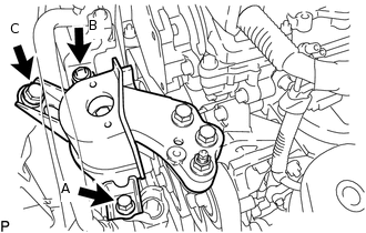
Tighten the 3 bolts.
Tip:Temporarily tighten bolt A, and then tighten the bolts in the following order: B, C and A.
Do not damage the suction tube sub-assembly.
95 N*m
969 kgf*cm
70 ft.*lbf
Connect the 2 clamps to the suction tube sub-assembly.
-
REMOVE ENGINE SUPPORT BRIDGE
Remove SST from the vehicle body.
Note:Prevent SST from contacting the vehicle body or windshield.
REMOVE ENGINE HANGER
-
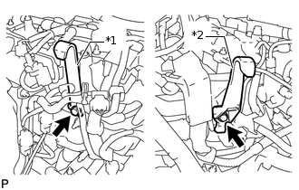
*1
No. 1 Engine Hanger
*2
No. 2 Engine Hanger
Remove the 2 bolts and No.1 and No. 2 engine hangers.
-
CONNECT RADIATOR RESERVE TANK ASSEMBLY
INSTALL REAR ENGINE UNDER COVER RH
INSTALL AIR CLEANER CASE
INSTALL AIR CLEANER FILTER ELEMENT SUB-ASSEMBLY
INSTALL AIR CLEANER CAP SUB-ASSEMBLY
INSTALL NO. 1 ENGINE COVER
INSTALL COWL TOP VENTILATOR LOUVER SUB-ASSEMBLY
INSTALL WINDSHIELD WIPER ARM AND BLADE ASSEMBLY RH
INSTALL WINDSHIELD WIPER ARM AND BLADE ASSEMBLY LH
INSTALL WINDSHIELD WIPER ARM COVER
INSPECT VACUUM PUMP OPERATION