CAMSHAFT INSTALLATION
CAUTION / NOTICE / HINT
Always be sure to check the tightening torque.
If the pressure lines are leaking after installation, they must be replaced.
Do not overtighten the pressure lines.
PROCEDURE
INSPECT VALVE LASH ADJUSTER ASSEMBLY
INSTALL VALVE LASH ADJUSTER ASSEMBLY
Install the 16 valve lash adjuster assemblies to the cylinder head sub-assembly.
Note:Install the valve lash adjuster assemblies to their original positions.
INSTALL NO. 1 VALVE ROCKER ARM SUB-ASSEMBLY
Install the 16 No. 1 valve rocker arm sub-assemblies.
INSTALL CAMSHAFT HOUSING SUB-ASSEMBLY
Install 4 new gaskets.
-
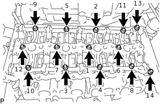
Uniformly tighten the 14 bolts in several steps in the sequence shown in the illustration.
Using an E10 "TORX" socket wrench, install the camshaft housing sub-assembly with the 14 bolts.
13 N*m
133 kgf*cm
10 ft.*lbf
SET NO. 1 CYLINDER TO TDC/COMPRESSION
INSTALL CAMSHAFT AND NO. 2 CAMSHAFT
Apply clean engine oil to the cam lobe of each camshaft, journals of the camshaft housing sub-assembly and No. 1 valve rocker arm sub-assemblies.
-
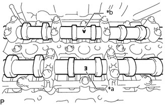
*a
Mark (E) (Intake Side)
*b
Mark (A) (Exhaust Side)
Place the camshaft and No. 2 camshaft on the camshaft housing sub-assembly as shown in the illustration so that mark (E) and mark (A) face upward.
Note: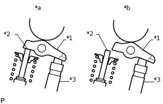
*1
No. 1 Valve Rocker Arm Sub-assembly
*2
Valve Stem
*3
Valve Lash Adjuster Assembly
*a
Correct
*b
Incorrect
Before and after setting the camshaft and No. 2 camshaft on the camshaft housing sub-assembly, check that the No. 1 valve rocker arm sub-assembly is correctly installed to the valve lash adjuster assembly.
-
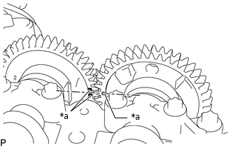
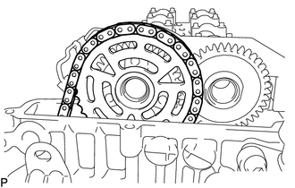
*a
Timing Mark
Align the camshaft and No. 2 camshaft timing marks.
-
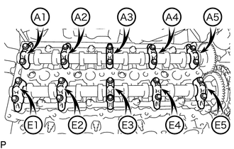
Set the 5 intake camshaft bearing caps and 5 exhaust camshaft bearing caps on the camshaft and No. 2 camshaft as shown in the illustration.
Using an E8 "TORX" socket wrench, temporarily install the 20 bolts.
-
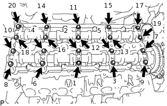
Uniformly tighten the 20 bolts in several steps in the sequence shown in the illustration.
10 N*m
102 kgf*cm
7 ft.*lbf
-
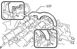
*a
No clearance
Using SST, hold the camshaft and No. 2 camshaft.
SST
PZ4TB-04961-12
Note:Make sure there is no clearance between SST and the camshaft housing sub-assembly.
-
Using an E10 "TORX" socket wrench, temporarily install the camshaft timing sprocket with No. 2 chain sub-assembly to the camshaft with the 3 bolts.
Step 1:
Tighten the 3 bolts.
10 N*m
102 kgf*cm
7 ft.*lbf
Step 2:
Loosen the 3 bolts 90°.
Using a T45 "TORX" socket wrench, install the No. 2 timing chain guide with the bolt.
20 N*m
204 kgf*cm
15 ft.*lbf
Using a 24 mm socket wrench, install the No. 2 chain tensioner assembly.
70 N*m
714 kgf*cm
52 ft.*lbf
Using an E10 "TORX" socket wrench, install the camshaft timing sprocket with the 3 bolts.
14 N*m
143 kgf*cm
10 ft.*lbf
Remove SST from the camshaft.
INSTALL NO. 2 ENGINE HANGER
INSTALL NO. 1 EXHAUST MANIFOLD HEAT INSULATOR
INSTALL NO. 1 TURBO INSULATOR
INSTALL CYLINDER HEAD COVER SUB-ASSEMBLY
Install 5 new gaskets to the cylinder head cover sub-assembly.
Install the cylinder head cover sub-assembly and tighten the 17 bolts.
Tip:Refer to "SPECIFICATIONS - STANDARD BOLT" for the tightening torque.
INSTALL OIL FILLER CAP SUB-ASSEMBLY
INSTALL VACUUM CONTROL VALVE BRACKET
INSTALL INJECTOR ASSEMBLY
INSTALL NOZZLE LEAKAGE PIPE ASSEMBLY
INSTALL CAMSHAFT POSITION SENSOR
INSTALL COMMON RAIL ASSEMBLY
INSTALL INJECTION PIPE SUB-ASSEMBLY
INSTALL FUEL INLET PIPE SUB-ASSEMBLY
INSTALL INTAKE MANIFOLD
INSTALL NO. 1 VACUUM PIPE
CONNECT NO. 2 VACUUM HOSE ASSEMBLY
INSTALL ENGINE OIL LEVEL DIPSTICK GUIDE
CONNECT ENGINE WIRE
INSTALL AIR CLEANER CASE SUB-ASSEMBLY
INSTALL AIR CLEANER CAP SUB-ASSEMBLY WITH AIR CLEANER HOSE ASSEMBLY
INSTALL ENGINE COVER
INSTALL DIESEL THROTTLE BODY ASSEMBLY
INSTALL RADIATOR ASSEMBLY
CONNECT CABLE TO NEGATIVE BATTERY TERMINAL
Note:When disconnecting the cable, some systems need to be initialized after the cable is reconnected.
INSPECT FOR FUEL LEAK
INSPECT FOR ENGINE OIL LEAK