CAN COMMUNICATION SYSTEM, Diagnostic DTC:U1110
| DTC Code | DTC Name |
|---|---|
| U1110 | Lost Communication with Clearance Sonar Module |
DESCRIPTION
DTC No. |
Detection Item |
DTC Detection Condition |
Trouble Area |
DTC Output from |
|---|---|---|---|---|
U1110 |
Lost Communication with Clearance Sonar Module |
There is no communication from the clearance warning ECU assembly. |
|
Power management control ECU |
For vehicles with a LEXUS parking assist-sensor system (without parking assist system and/or side monitor system) only.
WIRING DIAGRAM
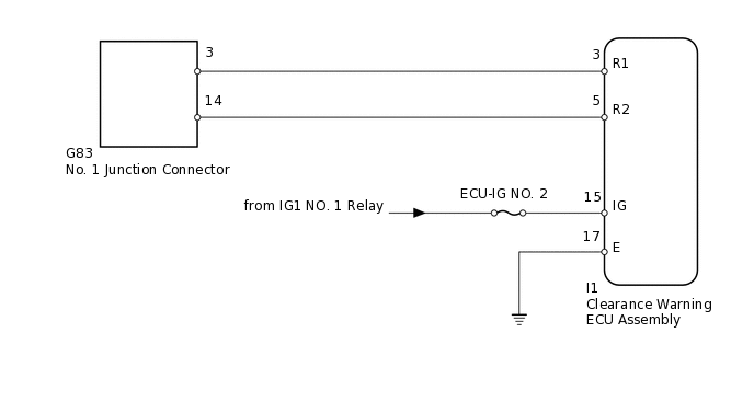
CAUTION / NOTICE / HINT
Inspect the fuses for circuits related to this system before performing the following inspection procedure.
Operating the engine switch, any switches or any doors triggers related ECU and sensor communication with the CAN, which causes resistance variation.
PROCEDURE
DISCONNECT CABLE FROM NEGATIVE BATTERY TERMINAL
Disconnect the cable from the negative (-) battery terminal before measuring the resistances of the main wire and branch wire.
CAUTION:Wait at least 90 seconds after disconnecting the cable from the negative (-) battery terminal to disable the SRS system.
Note:After turning the engine switch off, waiting time may be required before disconnecting the cable from the battery terminal. Therefore, make sure to read the disconnecting the cable from the battery terminal notice before proceeding with work.
When disconnecting the cable, some systems need to be initialized after the cable is reconnected.
Result
Result
NEXT
CHECK FOR OPEN IN CAN BUS WIRE (CLEARANCE WARNING ECU BRANCH WIRE)
-
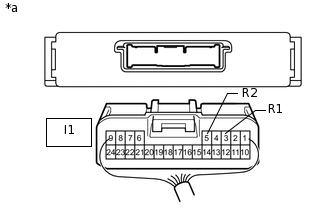
*a
Rear view of wire harness connector
(to Clearance Warning ECU Assembly)
Disconnect the I1 clearance warning ECU assembly connector.
Measure the resistance according to the value(s) in the table below.
Standard Resistance
Tester Connection
Switch Condition
Specified Condition
I1-3 (R1) - I1-5 (R2)
Engine switch off
54 to 69 Ω
Result
Result
OK
NG
NG REPAIR OR REPLACE CLEARANCE WARNING ECU BRANCH WIRE OR CONNECTOR (R1, R2)
-
CHECK HARNESS AND CONNECTOR (CLEARANCE WARNING ECU - BATTERY AND BODY GROUND)
-
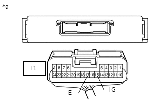
*a
Rear view of wire harness connector
(to Clearance Warning ECU Assembly)
Connect the cable to the negative (-) battery terminal.
Note:When disconnecting the cable, some systems need to be initialized after the cable is reconnected.
Measure the resistance according to the value(s) in the table below.
Standard Resistance
Tester Connection
Condition
Specified Condition
I1-17 (E) - Body ground
Always
Below 1 Ω
Measure the voltage according to the value(s) in the table below.
Standard Voltage
Tester Connection
Switch Condition
Specified Condition
I1-15 (IG) - Body ground
Engine switch on (IG)
11 to 14 V
Result
Result
OK
NG
NG REPAIR OR REPLACE HARNESS OR CONNECTOR
-