EMISSION CONTROL SYSTEM (w/ EGR System) ON-VEHICLE INSPECTION
Note
Always stop the engine when installing or removing the vacuum gauges, or removing the vacuum hoses.
Tech Tips
In a malfunction where the EGR system is always on, black or white smoke may emit from the exhaust pipe.
If this occurs, inspect the EGR system.
-
INSTALL VACUUM GAUGE
-
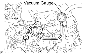
Using a 3-way connector, connect a vacuum gauge to the hose between the EGR valve and E-VRV.
-
-
CHECK SEATING OF EGR VALVE
-
Start the engine. Check that the engine starts and then idles.
-
-
CHECK OUTPUT VACUUM WITH VACUUM GAUGE
-
Connect a vacuum gauge to the output pipe.
-
Warm up the engine and check that the vacuum gauge reading is above 28.0 kPa (210 mmHg, 8.3 in.Hg).
If the result is not as specified, check for leaks between the EGR valve and vacuum pump, or check the EGR valve.
-
-
CHECK HOT ENGINE CONDITION
-
Visually check the vacuum hose between the vacuum pump and EGR valve for leaks.
-
Warm up the engine.
The coolant temperature should be above 75°C (167°F) and below 90°C (194°F).
-
Check that the vacuum gauge reading is more than 28.0 kPa (210 mmHg, 8.3 in.Hg) at idle.
-
Check that the vacuum gauge indicator reading increases by more than 28.0 kPa (210 mmHg, 8.3 in.Hg) at 1,500 rpm.
-
When the accelerator pedal is fully depressed quickly, check that the vacuum gauge indicator drops momentarily.
-
Keep the engine speed at more than 4,000 rpm.
-
Check that the vacuum gauge reading is as shown below.
Standard condition 3.6 kPa (28 mmHg, 1.1 in.Hg) -
When the accelerator pedal is released, check that the vacuum gauge indicator drops momentarily while the engine speed decreases from more than 4,000 rpm to idle.
If the result is not as specified, refer to the INSPECTION section Click here.
-
-
REMOVE VACUUM GAUGE
-
CHECK FOR LEAKS
-
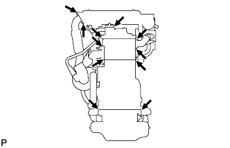
Visually check that the hoses, connections and gaskets have no cracks, leaks or damage.
Note
-
Detachment or other problems with the engine oil dipstick, filler cap, PCV hose and other components may cause the engine to run improperly.
-
Air suction caused by disconnections, looseness or cracks in the parts of the air induction system between the throttle body and cylinder head will cause engine failure or engine malfunctions.
If the result is not as specified, replace parts as necessary.
-
-
-
CHECK VACUUM PUMP ASSEMBLY
-
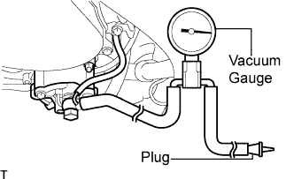
Disconnect the vacuum hose from the vacuum pump.
-
Connect the hose of a vacuum gauge to the pump.
-
Insert a plug into the other hose of the gauge.
-
Start the engine and warm it up for more than 2 minutes.
-
With the engine idling, measure the negative pressure of the pump.
Standard negative pressure More than 86.7 kPa (650 mmHg, 26 in.Hg) Tech Tips
The vacuum pump assembly is listed as one of the 200000 km (124000 mile) maintenance parts. Make sure to disassemble and inspect it every 200000 km (124000 miles) and replace parts as necessary.
-
Remove the gauge from the pump.
-
Connect the hose to the pump with the clip.
-