STOP LIGHT SWITCH INSTALLATION
PROCEDURE
INSTALL STOP LIGHT SWITCH MOUNTING ADJUSTER
Attach the 2 claws to install a new stop light switch mounting adjuster.
INSTALL STOP LIGHT SWITCH ASSEMBLY
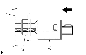
Install the stop light switch assembly to the adjuster until the switch body slightly touches the brake pedal.
Table 1. Text in Illustration *1
Brake Pedal
*2
Stop Light Switch Mounting Adjuster
*3
Stop Light Switch Assembly
Note:Do not depress the brake pedal.
-
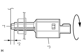
Rotate the stop light switch assembly clockwise so that the clearance is between 1.5 and 2.5 mm (0.0590 to 0.0984 in.) as shown in the illustration.
1.5 N*m
15 kgf*cm
13 in.*lbf
Table 2. Text in Illustration *1
Shaft
*2
1.5 to 2.5 mm (0.0590 to 0.0984 in.)
*3
Stop Light Switch Assembly
Note:Do not depress the brake pedal.
Check the stop light switch assembly clearance.
Stop light switch clearance
1.5 to 2.5 mm (0.0590 to 0.0984 in.)
Connect the connector to the stop light switch assembly.
INSTALL NO. 1 INSTRUMENT PANEL UNDER COVER SUB-ASSEMBLY