ENGINE UNIT
-
CONSTRUCTION
-
A 3-blade vane type VVT-iW controller (camshaft timing gear assembly) is used on the intake side.
-
When the engine stops, each camshaft timing gear assembly is locked at the most retarded angle by its lock pin. This ensures excellent engine startability.
-
An oil control valve is built into the camshaft timing gear bolt, which secures the vane to the intake camshaft (camshaft and No. 3 Camshaft Sub-assembly). As a result, the controlled oil passage is shortened to improve response performance and operation at low temperatures. The oil control valve switches the oil passage when pressed by the cam timing oil control solenoid assembly. Oil passage switching is controlled to continuously change the intake camshaft (camshaft and No. 3 Camshaft Sub-assembly) phase.
Figure 1. VVT-iW controller (Camshaft Timing Gear Assembly)
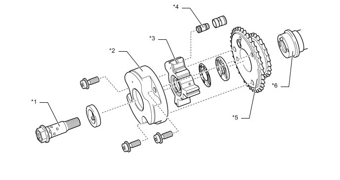
*1 Camshaft Timing Gear Bolt *2 Housing *3 Vane (Fixed on Intake Camshaft (Camshaft and No. 3 Camshaft Sub-assembly)) *4 Lock Pin *5 Camshaft Timing Gear Cover RR (Sprocket) *6 Intake Camshaft (Camshaft and No. 3 Camshaft Sub-assembly) Figure 2. Lock Pin
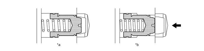
*a At a Stop *b In Operation 
Oil Pressure - - Figure 3. Camshaft Timing Gear Bolt (Built into Oil Control Valve)
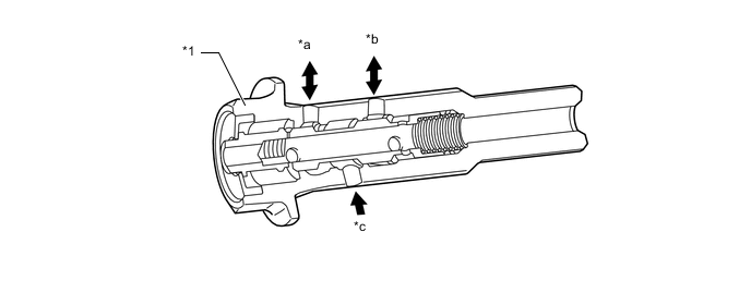
*1 Oil Control Valve - - *a To Retard Side Vane Chamber *b To Advance Side Vane Chamber *c Engine Oil - -
-
-
OPERATION
-
Advance
-
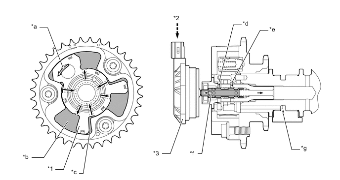
The cam timing oil control solenoid assembly operates according to the advance signal from the ECM assembly. When the oil control valve reaches the position shown in the following illustration, the advance side vane chamber of the VVT-iW controller (camshaft timing gear assembly) is affected by oil pressure and the vane inside the VVT-iW controller (camshaft timing gear assembly) rotates in the advanced direction. The intake camshaft (camshaft and No. 3 Camshaft Sub-assembly) fixed to the vane also rotates to the advanced side.
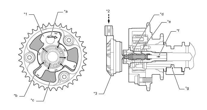
*1 Vane *2 ECM Assembly *3 Cam Timing Oil Control Solenoid Assembly - - *a Rotation Direction *b Retard Side Vane Chamber *c Advance Side Vane Chamber *d From Retard Side Vane Chamber *e To Advance Side Vane Chamber *f Drain *g Oil Pressure - - -
-
Retard
-
The cam timing oil control solenoid assembly operates according to the retard signal from the ECM assembly. When the oil control valve reaches the position shown in the following illustration, the retard side vane chamber of the VVT-iW controller (camshaft timing gear assembly) is affected by oil pressure and the vane inside the VVT-iW controller (camshaft timing gear assembly) rotates in the retarded direction. The intake camshaft (camshaft and No. 3 Camshaft Sub-assembly) fixed to the vane also rotates to the retarded side.
*1 Vane *2 ECM Assembly *3 Cam Timing Oil Control Solenoid Assembly - - *a Rotation Direction *b Retard Side Vane Chamber *c Advance Side Vane Chamber *d To Advance Side Vane Chamber *e From Retard Side Vane Chamber *f Drain *g Oil Pressure - - -
-
Hold
-
The ECM assembly calculates the target advanced angle according to driving conditions and performs control. After setting the target timing, timings are maintained by the neutral camshaft timing oil control valve assembly as long as driving conditions do not change. As a result, unnecessary engine oil discharge is suppressed while valve timings are aligned to the desired target position.
-
-