CYLINDER BLOCK INSPECTION
PROCEDURE
INSPECT CYLINDER BLOCK FOR WARPAGE
-
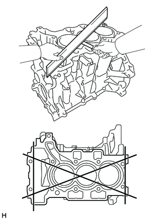
Using a precision straightedge and feeler gauge, check the surface which contacts the cylinder head gasket for warpage.
Maximum Warpage
0.05 mm (0.00197 in.)
If the warpage is more than the maximum, replace the cylinder block sub-assembly.
-
INSPECT CYLINDER BORE
-
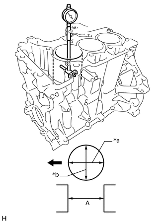
*a
Axial Direction
*b
Thrust Direction

Front
Using a cylinder gauge, measure the cylinder bore diameter at position (A) in the thrust and axial directions.
Standard Diameter
75.000 to 75.018 mm (2.95275 to 2.95346 in.)
If the average diameter of the 2 positions is more than the maximum, replace the cylinder block sub-assembly.
-
INSPECT PISTON
-
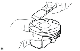
Using a gasket scraper, scrape off any carbon on the piston top.
-
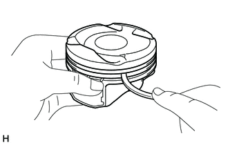
Using a groove cleaning tool or a broken ring, clean the piston ring grooves.
-
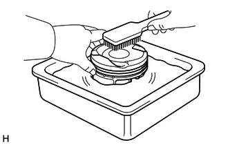
Using a brush and solvent, thoroughly clean the piston.
Note:Do not use a wire brush.
-
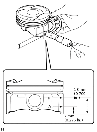
Using a micrometer, measure the piston diameter at a right angle to the piston center line where the distance from the bottom of the piston is as specified.
Standard
Distance
Diameter
A
74.969 to 74.979 mm (2.95153 to 2.95192 in.)
B
74.944 to 74.952 mm (2.95055 to 2.95086 in.)
If the diameter is less than the minimum, replace the piston sub-assembly.
-
INSPECT PISTON RING
-
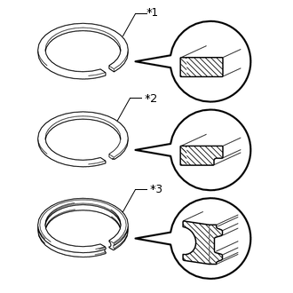
*1
No. 1 Compression Ring
*2
No. 2 Compression Ring
*3
Oil Ring
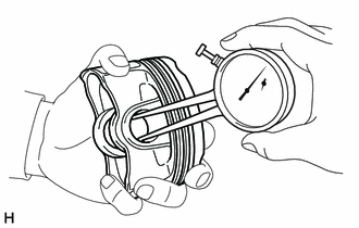
Inspect the piston ring set.
Standard
Item
Color Identification
Thickness
Ring Gap
No. 1 compression ring
Red
0.97 to 0.99 mm (0.0382 to 0.0390 in.)
0.18 to 0.28 mm (0.00709 to 0.0110 in.)
No. 2 compression ring
Blue
0.97 to 0.99 mm (0.0382 to 0.0390 in.)
0.4 to 0.6 mm (0.0157 to 0.0236 in.)
Oil ring
Yellow
1.97 to 1.99 mm (0.0776 to 0.0783 in.)
0.2 to 0.4 mm (0.00787 to 0.0157 in.)
-
INSPECT PISTON PIN OIL CLEARANCE
-
Using a caliper gauge, measure the inside diameter of the piston pin hole.
Standard Piston Pin Hole Inside Diameter
17.008 to 17.014 mm (0.66960 to 0.66984 in.)
-
Using a micrometer, measure the piston pin diameter.
Standard Piston Pin
Distance
Specified Condition
Diameter (A)
16.994 to 17.000 mm (0.66905 to 0.66929 in.)
Length (B)
50.8 to 51.2 mm (2.00 to 2.02 in.)
If the diameter and length are not as specified, replace the piston sub-assembly.
-
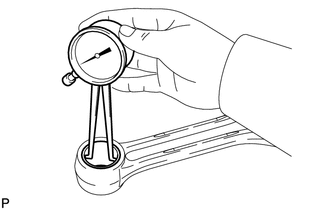
Using a caliper gauge, measure the inside diameter of the connecting rod small end bush.
Standard Connecting Rod Small End Bush Inside Diameter
16.96 to 16.976 mm (0.66772 to 0.66835 in.)
If the diameter is not as specified, replace the connecting rod.
-
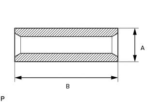
INSPECT CONNECTING ROD
-
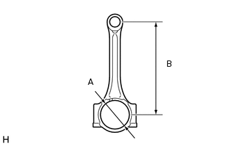
Inspect the connecting rod.
Standard
Distance
Specified Condition
A
45.000 to 45.016 mm (1.77165 to 1.77228 in.)
B
145.575 to 145.625 mm (5.73129 to 5.73326 in.)
-
INSPECT CRANKSHAFT
Inspect for runout.
Clean the crank journal.
Place the crankshaft on V-blocks.
-
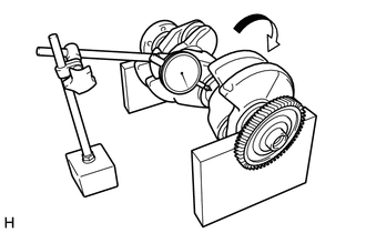
Using a dial indicator and V-blocks, measure the runout as shown in the illustration.
Maximum Runout
0.007 mm (0.000276 in.)
If the runout is more than the maximum, replace the crankshaft.
-
*a
Measurement Area
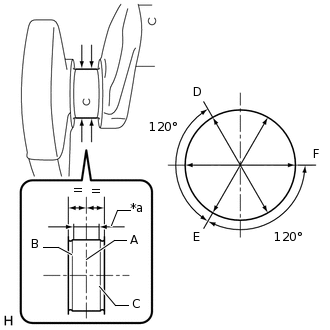
Inspect the main journals.
Using a micrometer, measure the diameter of each main journal.
Standard Main Journal Diameter
41.984 to 42.000 mm (1.65291 to 1.65354 in.)
Tip:The main journal diameter is the average diameter of the 3 measurements points (A), (B) and (C).
Each measurement point (A), (B) and (C) is the average diameter of the 3 measurement points (D), (E) and (F) which are 120° apart.
-
*a
Measurement Area
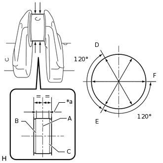
Inspect the crank pins.
Using a micrometer, measure the diameter of each crank pin.
Standard Crank Pin Diameter
41.984 to 42.000 mm (1.65291 to 1.65354 in.)
Tip:The main journal diameter is the average diameter of the 3 measurements points (A), (B) and (C).
Each measurement point (A), (B) and (C) is the average diameter of the 3 measurement points (D), (E) and (F) which are 120° apart.
-
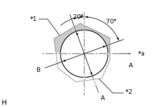
*1
Cylinder Block Sub-assembly
*2
Crankshaft Bearing Cap
*a
Exhaust Side
Measure the inner diameter of the cylinder block sub-assembly and crankshaft bearing cap.
Standard Diameter
45.600 to 45.619 mm (1.79527 to 1.79602 in.)
Tip:The inner diameter of the cylinder block sub-assembly and crankshaft bearing cap is the average diameter of the 2 measurement points (A) and (B)
INSPECT CRANKSHAFT BEARING
-
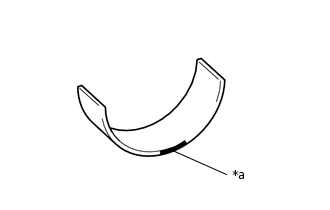
*a
Color
Inspect the crankshaft bearings.
Standard Bearing Thickness
Item
Position
Group
Color identification
Specified Condition
Crankshaft Bearing
1 and 4
-
-
1.798 mm (0.0708 in.)
2 and 3
-
Black
1.798 mm (0.0708 in.)
No. 2 Crankshaft Bearing
-
a
Brown
1.786 mm (0.0703 in.)
b
Blue
1.794 mm (0.0706 in.)
c
Green
1.802 mm (0.0709 in.)
d
Yellow
1.810 mm (0.0713 in.)
Tip:Check makes on the crankshaft and cylinder block sub-assembly for each cylinder. Refer to the matching table to select the bearing.
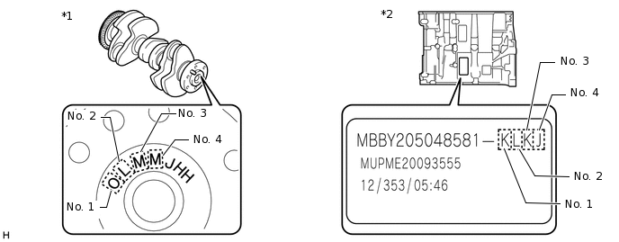
*1
Crankshaft
*2
Cylinder Block Sub-assembly
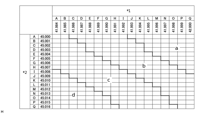
*1
Crankshaft (Main Journal)
*2
Cylinder Block Sub-assembly
-
INSPECT CONNECTING ROD BEARING
-
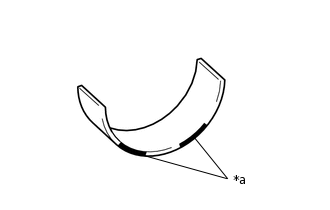
*a
Color
Inspect the connecting rod bearings.
Standard Bearing Thickness
Item
Group
Color Identification
Specified Condition
Connecting Rod Bearing (Upper)
-
-
1.492 to 1.498 mm (0.0587 to 0.0590 in.)
Connecting Rod Bearing (Lower)
a
Brown
1.479 to 1.485 mm (0.0582 to 0.0585 in.)
b
Blue
1.486 to 1.492 mm (0.0585 to 0.0587 in.)
c
Green
1.493 to 1.499 mm (0.0588 to 0.0590 in.)
d
Yellow
1.500 to 1.506 mm (0.0591 to 0.0593 in.)
Tip:Check makes on the crankshaft and connecting rod cap for each cylinder. Refer to the matching table to select the bearing.
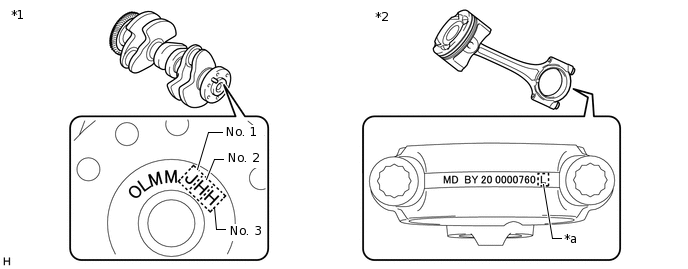
*1
Crankshaft
*2
Connecting Rod Cap
*a
Mark
-
-
*1
Crankshaft (Crank Pin)
*2
Connecting Rod (Small End)
-