MANUAL TRANSAXLE ASSEMBLY INSTALLATION
PROCEDURE
INSTALL MANUAL TRANSAXLE ASSEMBLY
Align the input shaft assembly with the clutch disc assembly and install the manual transaxle assembly to the engine.
Note:Make sure that the dowel pins are not loose, bent, damaged or scratched and then install the manual transaxle assembly to the engine with the contact surfaces of the engine and transaxle flat against each other.
-
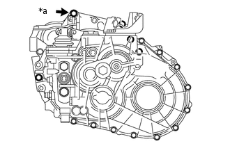
*a
Temporarily
Temporarily install the manual transaxle assembly with the bolt (*a).
-
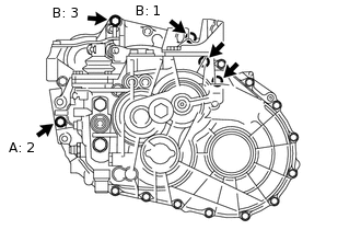
Tighten the 3 bolts labeled A and B in the order shown in the illustration, and then install the 2 bolts.
for bolt A
46 N*m
469 kgf*cm
34 ft.*lbf
for bolt B
64 N*m
653 kgf*cm
47 ft.*lbf
INSTALL STIFFENER PLATE LH
INSTALL STIFFENER PLATE RH
INSTALL OIL PAN INSULATOR
INSTALL ENGINE MOUNTING BRACKET LH
Tip:Perform this procedure only when replacement of the engine mounting bracket LH is necessary.
Install the engine mounting bracket LH with the 4 bolts.
64 N*m
653 kgf*cm
47 ft.*lbf
INSTALL REAR ENGINE MOUNTING BRACKET
Temporarily install the rear engine mounting bracket with the 5 bolts.
-
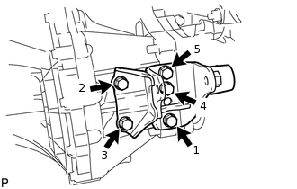
Tighten the 5 bolts of the rear engine mounting bracket in the order shown in the illustration.
45 N*m
459 kgf*cm
33 ft.*lbf
INSTALL FRONT ENGINE MOUNTING BRACKET
-
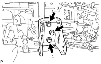
Temporarily install the front engine mounting bracket with the 3 bolts.
Tighten the 3 bolts of the front engine mounting bracket in the order shown in the illustration.
64 N*m
653 kgf*cm
47 ft.*lbf
-
INSTALL ENGINE ASSEMBLY WITH MANUAL TRANSAXLE