DIFFERENTIAL CASE DISASSEMBLY
PROCEDURE
INSPECT FRONT DIFFERENTIAL CASE ASSEMBLY WITH RING GEAR
INSPECT FRONT DIFFERENTIAL SIDE GEAR THRUST AMOUNT
REMOVE FRONT DIFFERENTIAL PINION SHAFT STRAIGHT PIN
Mount the front differential case in a vise between aluminum plates.
Note:Do not overtighten the vise.
-
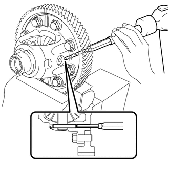
Using a 5 mm pin punch and hammer, remove the front differential pinion shaft straight pin from the front differential case assembly with ring gear.
REMOVE FRONT NO. 1 DIFFERENTIAL PINION SHAFT
-
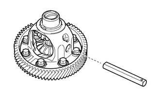
Remove the front No. 1 differential pinion shaft from the front differential case assembly with ring gear.
-
INSPECT FRONT DIFFERENTIAL PINION BACKLASH
REMOVE FRONT DIFFERENTIAL SIDE GEAR
Install SST as shown in the illustration and tighten it.
09528-52010
09528-05020
09953-05010
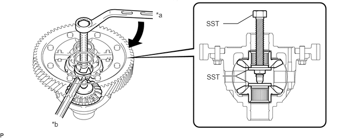
Table 1. Text in Illustration *a
Turn
*b
Hold
Note:Do not overtighten SST, as doing so will damage the front differential side gears, conical springs, front No. 1 differential side gear thrust washers and front differential case assembly with ring gear.
Tip:Tighten SST until there is clearance between the front differential pinions and front differential side gears.
When removing the front differential pinions, do not overtighten SST, as it is necessary to rotate the front differential side gears.
-
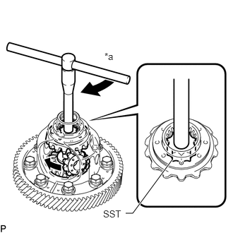
Install SST as shown in the illustration, rotate the front differential side gear, and then remove the 2 front differential pinions and 2 front differential pinion thrust washers from the front differential case assembly with ring gear.
09528-52010
09528-05040
Table 2. Text in Illustration *a
Turn
Note:Do not drop the differential pinion and front differential pinion thrust washer.
-
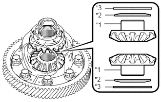
Remove SST from the front differential case assembly with ring gear, and then remove the 2 front differential side gears, 2 front No. 1 differential side gear thrust washers and 2 conical springs from the front differential case assembly with ring gear.
Table 3. Text in Illustration *1
Front Differential Side Gear
*2
Conical Spring
*3
Front No. 1 Differential Side Gear Thrust Washer
Note:Do not drop the front differential side gear, front No. 1 differential side gear thrust washer and conical spring.