LIGHTING SYSTEM LED open-circuit detection circuit
DESCRIPTION
the low beam headlights do not illuminate, or a communication malfunction is detected between the headlight assembly and headlight leveling ECU assembly.
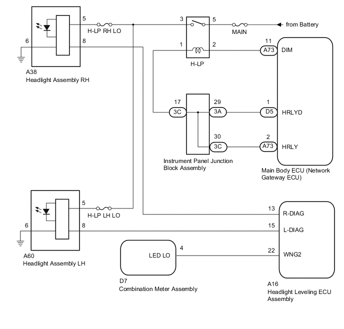
WIRING DIAGRAM
PROCEDURE
-
PERFORM ACTIVE TEST USING GTS (HEADLIGHT RELAY)
-
Connect the GTS to the DLC3.
-
Turn the ignition switch to ON.
-
Turn the GTS on.
-
Enter the following menus: Body / Main Body / Active Test.
-
Perform the Active Test according to the display on the GTS.
Main Body Tester Display Test Part Control Range Diagnostic Note Headlight Relay Headlight relay ON/OFF - OK The daytime running lights illuminate.
NG 
INSPECT H-LP RELAY Click here
OK 
-
-
CHECK HARNESS AND CONNECTOR (HEADLIGHT ASSEMBLY - HEADLIGHT LEVELING ECU ASSEMBLY)
-
Disconnect the A60 or A38 Headlight Assembly RH or LH connectors.
-
Disconnect the A16 headlight leveling ECU assembly connector.
-
Measure the resistance according to the value(s) in the table below.
Standard Resistance Tester Connection Condition Specified Condition A38-8 - A16-13 (R-DIAG) Always Below 1 Ω A60-8 - A16-15 (L-DIAG) Always Below 1 Ω A38-8 or A16-13 (R-DIAG) - Body ground Always 10 kΩ or higher A60-8 or A16-15 (L-DIAG) - Body ground Always 10 kΩ or higher
NG 
REPAIR OR REPLACE HARNESS OR CONNECTOR
OK
-
-
INSPECT HEADLIGHT LEVELING ECU ASSEMBLY
-
Measure the voltage according to the value(s) in the table below.

Standard Voltage Tester Connection Condition Specified Condition A16-13 (R-DIAG) - Body ground Always Below 1.5 V A16-15 (L-DIAG) - Body ground Always Below 1.5 V Text in Illustration *a Component without harness connected
(Headlight Leveling ECU Assembly)
OK
GO TO PROBLEM SYMPTOMS TABLE Click here
NG
REPLACE HEADLIGHT ASSEMBLY Click here
-
-
INSPECT H-LP RELAY
-
Remove the H-LP relay from the engine room relay block.
-
Inspect the H-LP relay Click here.
NG
REPLACE H-LP RELAY
OK
-
-
CHECK HARNESS AND CONNECTOR (ENGINE ROOM RELAY BLOCK - BATTERY)
-
Remove the H-LP relay from the engine room relay block.
-
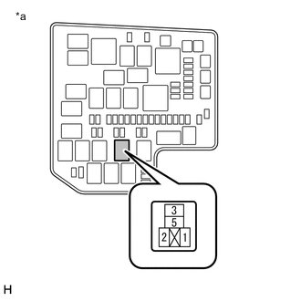
Text in Illustration *a Engine Room Relay Block
(H-LP Relay Terminal)
Measure the voltage according to the value(s) in the table below.
Standard Voltage Tester Connection Condition Specified Condition Relay Terminal 5 - Body ground Always 11 to 14 V
NG
REPAIR OR REPLACE HARNESS OR CONNECTOR
OK
-
-
CHECK HARNESS AND CONNECTOR (ENGINE ROOM RELAY BLOCK - MAIN BODY ECU (NETWORK GATEWAY ECU))
-
Remove the H-LP relay from the engine room relay block.
-
Disconnect the A73 main body ECU (network gateway ECU) connector.
-
Measure the resistance according to the value(s) in the table below.
Standard Resistance Tester Connection Condition Specified Condition Relay Terminal 2 - A73-11 Always Below 1 Ω A73-11 - Body ground Always 10 kΩ or higher
NG
REPAIR OR REPLACE HARNESS OR CONNECTOR
OK
-
-
CHECK HARNESS AND CONNECTOR (ENGINE ROOM RELAY BLOCK - INSTRUMENT PANEL JUNCTION BLOCK ASSEMBLY)
-
Remove the H-LP relay from the engine room relay block.
-
Disconnect the 3C Instrument panel junction block assembly connector.
-
Measure the resistance according to the value(s) in the table below.
Standard Resistance Tester Connection Condition Specified Condition Relay Terminal 1 - 3C-17 Always Below 1 Ω 3C-17 - Body ground Always 10 kΩ or higher
NG
REPAIR OR REPLACE HARNESS OR CONNECTOR
OK
-
-
CHECK HARNESS AND CONNECTOR (MAIN BODY ECU (NETWORK GATEWAY ECU) - INSTRUMENT PANEL JUNCTION BLOCK ASSEMBLY)
-
Disconnect the 3A and 3C Instrument panel junction block assembly connector.
-
Disconnect the A73 and D5 main body ECU (network gateway ECU) connector.
-
Measure the resistance according to the value(s) in the table below.
Standard Resistance Tester Connection Condition Specified Condition 3A-29 - D5-1 (HRLYD) Always Below 1 Ω 3C-30 - A73-2 (HRLY) Always Below 1 Ω 3A-29 or D5-1 (HRLYD) - Body ground Always 10 kΩ or higher 3C-30 or A73-2 (HRLY) - Body ground Always 10 kΩ or higher
NG
REPAIR OR REPLACE HARNESS OR CONNECTOR
OK
-
-
INSPECT INSTRUMENT PANEL JUNCTION BLOCK ASSEMBLY
-
Remove the instrument panel junction block assembly (See page ).
-
Remove the main body ECU (network gateway ECU) from the instrument panel junction block assembly.
-
Measure the resistance according to the value(s) in the table below.
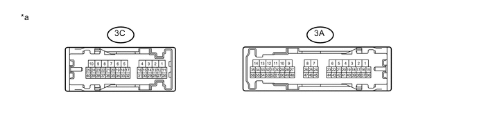
Standard Resistance Tester Connection Condition Specified Condition 3C-17 - 3A-29 Always Below 1 Ω 3C-17 - 3C-30 Always Below 1 Ω Text in Illustration *a Component without harness connected
(Instrument Panel Junction Block Assembly)
- -
OK
REPLACE MAIN BODY ECU (NETWORK GATEWAY ECU) Click here
NG
REPLACE INSTRUMENT PANEL JUNCTION BLOCK ASSEMBLY
-