EXHAUST MANIFOLD W/ TURBOCHARGER INSTALLATION
PROCEDURE
INSTALL STUD BOLT
Tip:If a stud bolt is deformed or the threads are damaged, replace it.
For turbocharger sub-assembly:
-
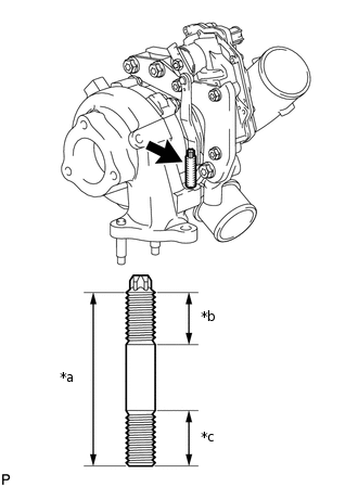
*a
47 mm (1.85 in.)
*b
14 mm (0.551 in.)
*c
15 mm (0.591 in.)
Using an E8 "TORX" wrench, install the stud bolt to the turbocharger sub-assembly.
8.0 N*m
82 kgf*cm
71 in.*lbf
-
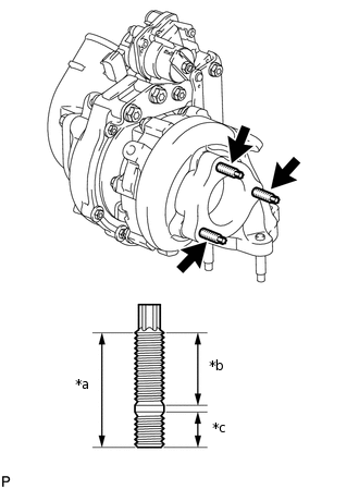
*a
32 mm (1.26 in.)
*b
20 mm (0.787 in.)
*c
10 mm (0.394 in.)
Using an E8 "TORX" wrench, install the 3 stud bolts to the turbocharger sub-assembly.
10 N*m
102 kgf*cm
7 ft.*lbf
-
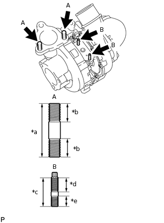
*a
43 mm (1.69 in.)
*b
16 mm (0.630 in.)
*c
24.5 mm (0.965 in.)
*d
12 mm (0.472 in.)
*e
9.0 mm (0.354 in.)
Install the 2 stud bolts (A).
20 N*m
204 kgf*cm
15 ft.*lbf
Using an E5 "TORX" wrench, install the 2 stud bolts (B).
5.0 N*m
51 kgf*cm
44 in.*lbf
-
-
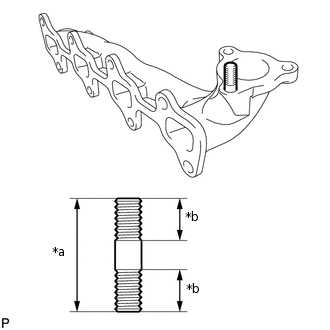
*a
43 mm (1.69 in.)
*b
16 mm (0.630 in.)
For exhaust manifold:
Install the stud bolt to the exhaust manifold.
20 N*m
204 kgf*cm
15 ft.*lbf
INSTALL EXHAUST MANIFOLD AND TURBOCHARGER SUB-ASSEMBLY
-
*1
Collar
*2
Groove
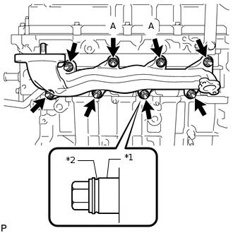
Temporarily install a new gasket, the exhaust manifold, and 2 collars with 2 new nuts (A). Tighten the nuts until the mating surface of the exhaust manifold contacts the cylinder head.
Temporarily install the 6 collars with 6 new nuts.
Tip:When installing the collars, pay attention to the mounting orientation. The ring groove of the collar should be on the outside. Refer to the illustration.
Do not fully tighten the nuts as doing so may result in misalignment of the exhaust manifold.
Install a new gasket and the turbocharger with 3 new nuts.
60 N*m
612 kgf*cm
44 ft.*lbf
-
*1
New Turbocharger Stay
*2
Collar
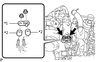
Install the 2 collars and a new turbocharger stay with 2 new nuts.
36 N*m
367 kgf*cm
27 ft.*lbf
Note:Do not reuse the turbocharger stay.
When installing the turbocharger stay, be sure to tighten the nut (A) first.
Tighten the 8 nuts of the exhaust manifold.
47 N*m
479 kgf*cm
35 ft.*lbf
-
INSTALL TURBO OIL OUTLET PIPE
Install a new gasket and the turbo oil outlet pipe with the 3 nuts.
11 N*m
112 kgf*cm
8 ft.*lbf
Connect the turbo oil outlet pipe and a new gasket with the union bolt.
35 N*m
357 kgf*cm
26 ft.*lbf
INSTALL NO. 3 WATER BY-PASS HOSE
Install the No. 3 water by-pass hose and slide the 2 clips to secure it.
INSTALL NO. 2 VACUUM TRANSMITTING PIPE SUB-ASSEMBLY
Install the No. 2 vacuum transmitting pipe with the bolt.
21 N*m
214 kgf*cm
15 ft.*lbf
Connect the 2 vacuum transmitting hoses.
INSTALL TURBOCHARGER WIRE
Install the turbocharger wire and engage the 3 wire harness clamps.
Connect the 2 connectors.
INSTALL NO. 2 TURBO OIL OUTLET PIPE
Install a new gasket and the No. 2 turbo oil outlet pipe with the 2 bolts.
11 N*m
112 kgf*cm
8 ft.*lbf
INSTALL TURBO OIL OUTLET HOSE
Install the turbo oil outlet hose and slide the 2 clips to secure it.
INSTALL NO. 1 TURBO INSULATOR
Install the No. 1 turbo insulator with the 2 bolts.
20.5 N*m
209 kgf*cm
15 ft.*lbf
INSTALL EGR PIPE WITH COOLER SUB-ASSEMBLY
PERFORM TURBOCHARGER INITIALIZATION