AUDIO AND VISUAL SYSTEM(for Radio and Display Type), Diagnostic DTC:B15D3
| DTC Code | DTC Name |
|---|---|
| B15D3 | Stereo Component Amplifier Disconnected |
DESCRIPTION
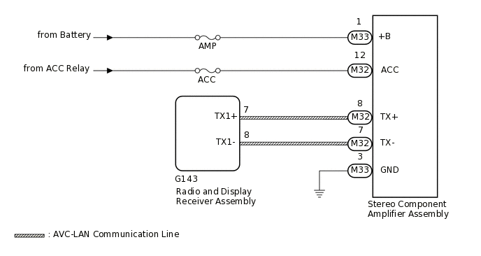
The radio and display receiver assembly and stereo component amplifier assembly are connected by the AVC-LAN communication line.
This DTC is stored when an AVC-LAN communication error occurs between the radio and display receiver assembly and stereo component amplifier assembly.
DTC No. |
Detection Item |
DTC Detection Condition |
Trouble Area |
|---|---|---|---|
B15D3 |
Stereo Component Amplifier Disconnected |
When either condition below is met:
|
|
The radio and display receiver assembly is the master unit.
WIRING DIAGRAM
CAUTION / NOTICE / HINT
Inspect the fuses for circuits related to this system before performing the following procedure.
PROCEDURE
CHECK FOR DTC
If DTC B15C3 is output, perform troubleshooting for DTC B15C3 first.
Body Electrical > Navigation System > Trouble Codes
OK
DTC B15C3 is not output.
Result
Proceed to
OK
NG
CHECK OPTIONAL COMPONENTS (INCLUDING ASSOCIATED WIRING)
Check that optional components (including associated wiring) which generate radio waves are not installed.
Result
Result
Proceed to
Optional components (including associated wiring) are installed
A
Optional components (including associated wiring) are not installed
B
Tip:Electrical noise from radio waves generated by optional components or the wiring for those components may affect AVC-LAN communication.
This DTC may be stored when an AVC-LAN communication error occurs due to electrical noise.
B CHECK FOR DTCClick here
REMOVE OPTIONAL COMPONENTS (INCLUDING ASSOCIATED WIRING)
Remove optional components (including associated wiring).
Note:Do not remove optional components or associated wiring without the permission of the customer.
Result
Proceed to
NEXT
CHECK FOR DTC
Clear the DTCs.
Body Electrical > Navigation System > Clear DTCs
Check for DTCs.
Body Electrical > Navigation System > Trouble Codes
OK
No DTCs are output.
Result
Proceed to
OK
NG
OK END (OPTIONAL COMPONENTS [INCLUDING ASSOCIATED WIRING] IS DEFECTIVE)
CHECK HARNESS AND CONNECTOR (STEREO COMPONENT AMPLIFIER ASSEMBLY - BATTERY AND BODY GROUND)
-
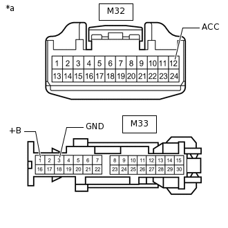
*a
Front view of wire harness connector
(to Stereo Component Amplifier Assembly)
Disconnect the stereo component amplifier assembly connectors.
Measure the resistance according to the value(s) in the table below.
Standard Resistance
Tester Connection
Condition
Specified Condition
M33-3 (GND) - Body ground
Always
Below 1 Ω
Measure the voltage according to the value(s) in the table below.
Standard Voltage
Tester Connection
Condition
Specified Condition
M33-1 (+B) - Body ground
Always
11 to 14 V
M32-12 (ACC) - Body ground
Ignition switch ACC
11 to 14 V
Ignition switch off
Below 1 V
Result
Proceed to
OK
NG
NG REPAIR OR REPLACE HARNESS OR CONNECTOR
-
CHECK HARNESS AND CONNECTOR (RADIO AND DISPLAY RECEIVER ASSEMBLY - STEREO COMPONENT AMPLIFIER ASSEMBLY)
Disconnect the G143 radio and display receiver assembly connector.
Disconnect the M32 stereo component amplifier assembly connector.
Measure the resistance according to the value(s) in the table below.
Standard Resistance
Tester Connection
Condition
Specified Condition
G143-7 (TX1+) - M32-8 (TX+)
Always
Below 1 Ω
G143-8 (TX1-) - M32-7 (TX-)
Always
Below 1 Ω
G143-7 (TX1+) - Body ground
Always
10 kΩ or higher
G143-8 (TX1-) - Body ground
Always
10 kΩ or higher
Result
Proceed to
OK
NG
NG REPAIR OR REPLACE HARNESS OR CONNECTOR
CHECK STEREO COMPONENT AMPLIFIER ASSEMBLY
Replace the stereo component amplifier assembly.
Clear the DTCs.
Body Electrical > Navigation System > Clear DTCs
Check for DTCs.
Body Electrical > Navigation System > Trouble Codes
OK
No DTCs are output.
Result
Proceed to
OK
NG
OK END (STEREO COMPONENT AMPLIFIER ASSEMBLY IS DEFECTIVE)