REAR SHOCK ABSORBER INSTALLATION
CAUTION / NOTICE / HINT
Use the same procedure for the RH and LH sides.
The procedure listed below is for the LH side.
PROCEDURE
TEMPORARILY INSTALL REAR NO. 1 SHOCK ABSORBER BRACKET LH
-
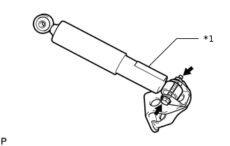
*1
Protector
Temporarily install the rear No. 1 shock absorber bracket LH to the rear shock absorber assembly LH with the bolt and nut.
Note:The absorber should be assembled with the protector positioned facing the front side of vehicle.
Tip:The bolts can be installed in either direction, however, make sure that they are both installed in the same direction.
-
TEMPORARILY INSTALL REAR SHOCK ABSORBER ASSEMBLY LH
Support the rear No. 2 suspension arm assembly LH with a jack using a wooden block to avoid damage.
-
Temporarily install the shock absorber upper side to the suspension member with the bolt and nut.
Tip:The bolts can be installed in either direction, however, make sure that they are both installed in the same direction.
-
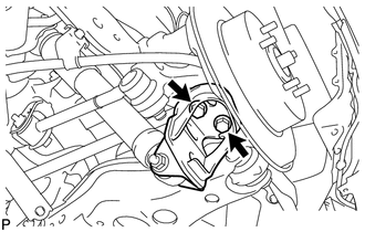
Install the rear No. 1 shock absorber bracket LH to the rear axle carrier with the 2 bolts.
80 N*m
816 kgf*cm
59 ft.*lbf
STABILIZE SUSPENSION
-
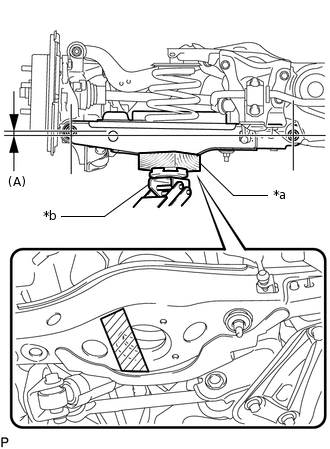
*a
Wooden Block
*b
Jack

Jack Point
Jack up the rear No. 2 suspension arm assembly LH, placing a wooden block underneath to avoid damage. Apply load to the suspension so that the rear No. 2 suspension arm assembly LH is positioned as shown in the illustration.
Standard length (A)
4.4 mm (0.1732 in.)
Note:Do not jack up the rear No. 2 suspension arm assembly LH too high as the vehicle may fall.
Tip:If the rear No. 2 suspension arm assembly LH cannot be positioned as shown in the illustration even when the rear No. 2 suspension arm assembly LH is jacked up, apply additional load by placing a weight in the luggage compartment.
Use the same procedure for the RH and LH sides.
-
TIGHTEN REAR SHOCK ABSORBER ASSEMBLY LH
-
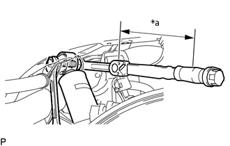
*a
Torque Wrench Fulcrum Length
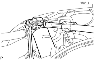
Tighten the bolt on the rear shock absorber assembly LH (upper side).
Specified tightening torque
80 N*m
816 kgf*cm
59 ft.*lbf
Note:Since a stopper nut is used, tighten the bolt.
Tip:Calculate the torque wrench reading when changing the fulcrum length of the torque wrench.
When using a ball joint lock nut wrench (fulcrum length of 149 mm (5.866 in.)) + torque wrench (fulcrum length of 255 mm (10.039 in.)): 50.5 N*m (515 kgf*cm, 37 ft.*lbf)
Tighten the bolt on the rear shock absorber assembly LH (lower side).
80 N*m
816 kgf*cm
59 ft.*lbf
Note:Since a stopper nut is used, tighten the bolt.
-
INSTALL REAR SUSPENSION ARM COVER LH (w/ Cover)
INSTALL REAR WHEEL
INSPECT AND ADJUST REAR WHEEL ALIGNMENT