WINDOW DEFOGGER SYSTEM TERMINALS OF ECU
CHECK HEATER CONTROL SUB-ASSEMBLY (for Manual Air Conditioning System)

Disconnect the H65 heater control connector.
Measure the voltage and resistance according to the value(s) in the table below.
Terminal No. (Symbol)
Wiring Color
Terminal Description
Condition
Specified Condition
H65-3 (IG+) - H65-5 (E)
Y - W-B
Power source (IG)
Ignition switch ON
11 to 14 V
H65-3 (IG+) - H65-5 (E)
Ignition switch off
Below 1 V
H65-5 (E) - Body ground
W-B - Body ground
Ground
Always
Below 1 Ω
If the result is not as specified, there may be a malfunction in the wire harness.
Reconnect the H65 heater control connector.
Measure the voltage according to the value(s) in the table below.
Terminal No. (Symbol)
Wiring Color
Terminal Description
Condition
Specified Condition
H65-2 (RDEF) - H65-5 (E)
B - W-B
Rear defogger signal
Ignition switch ON, rear window defogger switch off
11 to 14 V
H65-2 (RDEF) - H65-5 (E)
Ignition switch ON, rear window defogger switch on
Below 1 V
If the result is not as specified, there may be a malfunction in the heater control.
CHECK AIR CONDITIONING AMPLIFIER ASSEMBLY

Disconnect the H46 air conditioning amplifier connector.
Measure the voltage and resistance according to the value(s) in the table below.
Terminal No. (Symbol)
Wiring Color
Terminal Description
Condition
Specified Condition
H46-1 (IG+) - H46-14 (GND)
Y - W-B
Power source (IG)
Ignition switch ON
11 to 14 V
H46-1 (IG+) - H46-14 (GND)
Ignition switch off
Below 1 V
H46-21 (B) - H46-14 (GND)
W - W-B
Power source (Back-up)
Always
11 to 14 V
H46-14 (GND) - Body ground
W-B - Body ground
Ground
Always
Below 1 Ω
If the result is not as specified, there may be a malfunction in the wire harness.
Reconnect the H46 air conditioning amplifier connector.
Measure the voltage according to the value(s) in the table below.
Terminal No. (Symbol)
Wiring Color
Terminal Description
Condition
Specified Condition
H46-38 (RDFG) - H46-14 (GND)
B - W-B
Rear defogger signal
Ignition switch ON, rear window defogger switch off
11 to 14 V
H46-38 (RDFG) - H46-14 (GND)
Ignition switch ON, rear window defogger switch on
Below 1 V
If the result is not as specified, there may be a malfunction in the air conditioning amplifier.
CHECK AIR CONDITIONING CONTROL ASSEMBLY (for Automatic Air Conditioning System)

Disconnect the H21 air conditioning control connector.
Measure the voltage and resistance according to the value(s) in the table below.
Terminal No. (Symbol)
Wiring Color
Terminal Description
Condition
Specified Condition
H21-2 (IG+) - H21-5 (GND)
R - BR
Power source (IG)
Ignition switch ON
11 to 14 V
H21-2 (IG+) - H21-5 (GND)
Ignition switch off
Below 1 V
H21-5 (GND) - Body ground
BR - Body ground
Ground
Always
Below 1 Ω
If the result is not as specified, there may be a malfunction in the wire harness.
CHECK MAIN BODY ECU (INSTRUMENT PANEL JUNCTION BLOCK ASSEMBLY)
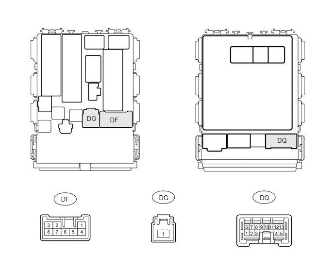
Disconnect the DG main body ECU connector.
Measure the voltage according to the value(s) in the table below.
Terminal No. (Symbol)
Wiring Color
Terminal Description
Condition
Specified Condition
DG-1 - Body ground
W - Body ground
Power source
Always
11 to 14 V
If the result is not as specified, there may be a malfunction in the wire harness.
Reconnect the DG main body ECU connector.
Measure the voltage according to the value(s) in the table below.
Terminal No. (Symbol)
Wiring Color
Terminal Description
Condition
Specified Condition
DQ-12 - Body ground
B - Body ground
DEF relay operation signal
Ignition switch ON, rear window defogger switch off
11 to 14 V
DQ-12 - Body ground
Ignition switch ON, rear window defogger switch on
Below 1 V
DF-2 - Body ground
B - Body ground
Defogger wire operation signal
Ignition switch ON, rear window defogger switch off
Below 1 V
DF-2 - Body ground
Ignition switch ON, rear window defogger switch on
11 to 14 V
If the result is not as specified, there may be a malfunction in the main body ECU.