SFI SYSTEM, Diagnostic DTC:P1235
| DTC Code | DTC Name |
|---|---|
| P1235 | High Pressure Fuel Pump Circuit |
DESCRIPTION
The fuel pump assembly (for high pressure) is attached to the insulator, which is attached to the cylinder head cover. The pump activates according to the position of the cam on the intake side camshaft (bank 2).
The fuel pump assembly (for high pressure) increases the pressure of the fuel supplied from the fuel pump in the fuel tank to the specified fuel pressure according to the operating condition, and it feeds the fuel to the fuel delivery pipe.
| DTC No. | DTC Detection Condition | Trouble Area |
|---|---|---|
| P1235 | When fuel pump for high pressure is operating, the diagnostic signal from injector driver (EDU) does not change (open or short in the fuel pump (for high pressure) circuit). (1 trip detection logic) |
|
CONFIRMATION DRIVING PATTERN
-
Connect the GTS to the DLC3.
-
Turn the ignition switch to ON and turn the GTS on.
-
Record the Freeze Frame Data.
-
Clear the DTCs (even if no DTCs are stored, perform the clear DTC procedure) Click here.
-
Turn the ignition switch off and wait for at least 30 seconds.
-
Turn the ignition switch to ON and turn the GTS on.
-
Based on engine speed, engine load and other freeze frame data stored in the ECM, reproduce the conditions present when the DTC was stored.
-
Enter the following menus: Powertrain / Engine / Trouble Codes.
-
Read the DTC.
Tech Tips
-
If a DTC is output, the system is malfunctioning.
-
If a DTC is not output, perform the following procedure.
-
-
Enter the following menus: Powertrain / Engine / Utility / All Readiness.
-
Input the DTC: P1235.
-
Check the DTC judgment result.
GTS Display Description NORMAL
-
DTC judgment completed
-
System normal
ABNORMAL
-
DTC judgment completed
-
System abnormal
INCOMPLETE
-
DTC judgment not completed
-
Perform driving pattern after confirming DTC enabling conditions
N/A
-
Unable to perform DTC judgment
-
Number of DTCs which do not fulfill DTC preconditions has reached ECU's memory limit
Tech Tips
-
If the judgment result shown ABNORMAL, the system has a malfunction.
-
If the judgment result shows NORMAL, the system is normal.
-
-
If the test result is INCOMPLETE or N/A and no DTC is output, perform a universal trip and check for permanent DTCs Click here.
Tech Tips
-
If a permanent DTC is output, the system is malfunctioning.
-
If no permanent DTC is output, the system is normal.
-
WIRING DIAGRAM
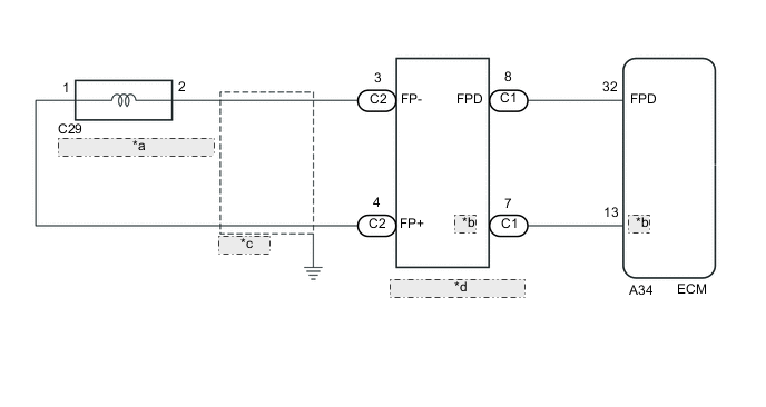
| *a | Fuel Pump Assembly (for High Pressure) |
| *b | FPF |
| *c | Shielded |
| *d | Injector Driver (EDU) |
CAUTION / NOTICE / HINT
Tech Tips
-
If the current from the INJ relay is cut because DTC P062D is stored, DTC P1235 will be stored even if the fuel pump assembly (for high pressure) is normal.
-
Read freeze frame data using the GTS. The ECM records vehicle and driving condition information as freeze frame data the moment a DTC is stored. When troubleshooting, freeze frame data can help determine if the vehicle was moving or stationary, if the engine was warmed up or not, if the air fuel ratio was lean or rich, and other data from the time the malfunction occurred.
PROCEDURE
-
INSPECT FUEL PUMP ASSEMBLY (FOR HIGH PRESSURE)
-
Inspect the fuel pump assembly (for high pressure) Click here.
NG 
REPLACE FUEL PUMP ASSEMBLY (FOR HIGH PRESSURE) Click here
OK 
-
-
CHECK HARNESS AND CONNECTOR (INJECTOR DRIVER (EDU) - FUEL PUMP ASSEMBLY)
-
Disconnect the injector driver (EDU) connector.
-
Disconnect the fuel pump assembly (for high pressure) connector.
-
Measure the resistance according to the value(s) in the table below.
Standard Resistance (Check for open) Tester Connection Condition Specified Condition C2-3 (FP-) - C29-2 Always Below 1 Ω C2-4 (FP+) - C29-1 Always Below 1 Ω Standard Resistance (Check for short) Tester Connection Condition Specified Condition C2-3 (FP-) or C29-2 - Body ground Always 10 kΩ or higher C2-4 (FP+) or C29-1 - Body ground Always 10 kΩ or higher
NG
REPAIR OR REPLACE HARNESS OR CONNECTOR
OK
-
-
CHECK HARNESS AND CONNECTOR (ECM - INJECTOR DRIVER (EDU))
-
Disconnect the ECM connector.
-
Disconnect the injector driver (EDU) connector.
-
Measure the resistance according to the value(s) in the table below.
Standard Resistance (Check for open) Tester Connection Condition Specified Condition A34-32 (FPD) - C1-8 (FPD) Always Below 1 Ω A34-13 (FPF) - C1-7 (FPF) Always Below 1 Ω Standard Resistance (Check for short) Tester Connection Condition Specified Condition A34-32 (FPD) or C1-8 (FPD) - Body ground Always 10 kΩ or higher A34-13 (FPF) or C1-7 (FPF) - Body ground Always 10 kΩ or higher
NG
REPAIR OR REPLACE HARNESS OR CONNECTOR
OK
-
-
INSPECT ECM (FPD VOLTAGE)
-
Turn the ignition switch to ON.
-
Inspect the ECM using an oscilloscope.
-

Text in Illustration *a Component with harness connected
(ECM)
*b FPD Terminal Waveform Normal Waveform While idling the engine, check the waveform the terminals of the ECM connector.
ECM Terminal Name A34-32 (FPD) - Body ground Tester Range 2 V/DIV., 20 ms./DIV. Condition Idling Standard Signal waveform appears as shown in the illustration. Tech Tips
The FPD terminal waveform is output only right after the engine starts. If this DTC is stored when the engine is started from ignition switch off, the system enters fail-safe mode and the waveform is not output.
-
NG 
INSPECT ECM (FPD VOLTAGE) Click here
OK
-
-
INSPECT ECM (FPF VOLTAGE)
-
Turn the ignition switch to ON.
-
Inspect the ECM using an oscilloscope.
-
While idling the engine, check the waveform the terminals of the ECM connector.
ECM Terminal Name CH1: A34-32 (FPD) - Body ground
CH2: A34-13 (FPF) - Body ground
Tester Range 2 V/DIV., 20 ms./DIV. Condition Idling 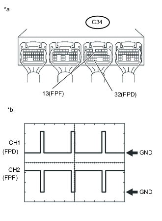
Text in Illustration *a Component with harness connected
(ECM)
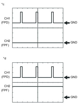
*b FPD Terminal and FPF Terminal Waveform Normal Waveform *c FPF Terminal Waveform NG Waveform 1 *d FPF Terminal Waveform NG Waveform 2 Tech Tips
*: If the FPF terminal waveform is similar to the FPF terminal waveform NG waveform 1, stop the engine and disconnect injector driver (EDU) connector. Then, while cranking the engine, check to see if there is a difference between the FPF terminal waveform and the previous one.
Result FPD Terminal Waveform FPF Terminal Waveform Proceed to OK OK A OK NG waveform 1* Does not change from NG waveform 1 (FPF terminal waveform remains at GND even after disconnecting the injector driver (EDU) connector and cranking the engine) A Changes to NG waveform 2 (FPF terminal waveform rises from GND after disconnecting the injector driver (EDU) connector and cranking the engine) B OK NG waveform 2 B -
A
REPLACE ECM Click here
B
REPLACE INJECTOR DRIVER (EDU) Click here
-
-
INSPECT ECM (FPD VOLTAGE)
-
Turn the ignition switch to ON.
-
Disconnect the injector driver (EDU) connector.
-
Inspect the ECM using an oscilloscope.
-
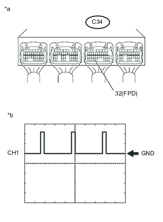
Text in Illustration *a Component with harness connected
(ECM)
*b FPD Terminal Waveform Normal Waveform While cranking the engine, check the waveform the terminals of the ECM connector.
ECM Terminal Name A34-32 (FPD) - Body ground Tester Range 2 V/DIV., 20 ms./DIV. Condition Cranking Standard Signal waveform appears as shown in the illustration.
-
OK
REPLACE INJECTOR DRIVER (EDU) Click here
NG
REPLACE ECM Click here
-