VEHICLE STABILITY CONTROL SYSTEM, Diagnostic DTC:C1268
| DTC Code | DTC Name |
|---|---|
| C1268 | Transfer L4 Position Switch Circuit |
DESCRIPTION
| DTC Code | DTC Detection Condition | Trouble Area |
|---|---|---|
| C1268 | No signal is input to the EXI4 terminal of the skid control ECU. |
|
WIRING DIAGRAM
INSPECTION PROCEDURE
Note
-
After replacing the brake actuator assembly, perform calibration Click here.
-
Before disconnecting the connector, make sure that there are no problems with the connection.
-
After disconnecting the connector, make sure that the connector case and terminals are not deformed or corroded.
PROCEDURE
-
CHECK TERMINAL VOLTAGE (EXI4 TERMINAL)
-
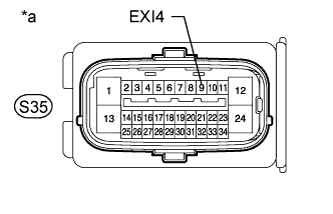
Text in Illustration *a Front view of wire harness connector
(to Skid Control ECU [Brake Actuator Assembly])
Connect the skid control ECU (brake actuator assembly) connector.
-
Set the vehicle to the L4 state using the transfer shift lever.
-
Disconnect the skid control ECU (brake actuator assembly) connector.
-
Measure the voltage according to the value(s) in the table below.
Standard Voltage Tester Connection Condition Specified Condition S35-9 (EXI4) - Body ground
-
Ignition switch ON
-
Transfer shift position L4
Below 1.5 V -
-
Connect the skid control ECU (brake actuator assembly) connector.
-
Set the vehicle to the H4 or H2 state using the transfer shift lever.
-
Disconnect the skid control ECU (brake actuator assembly) connector.
-
Measure the voltage according to the value(s) in the table below.
Standard Voltage Tester Connection Condition Specified Condition S35-9 (EXI4) - Body ground
-
Ignition switch ON
-
Transfer shift position not L4
11 to 14 V -
NG 
CHECK HARNESS AND CONNECTOR (SKID CONTROL ECU - L4 POSITION SWITCH) Click here
OK 
-
-
RECONFIRM DTC
-
Clear the DTC Click here.
-
Turn the ignition switch off.
-
Check if the same DTC is output.
Result Result Proceed to DTC is not output A DTC is output for LHD B for RHD C
B 
REPLACE BRAKE ACTUATOR ASSEMBLY Click here
C
REPLACE BRAKE ACTUATOR ASSEMBLY Click here
A 
USE SIMULATION METHOD TO CHECK Click here
-
-
CHECK HARNESS AND CONNECTOR (SKID CONTROL ECU - L4 POSITION SWITCH)
-
Turn the ignition switch off.
-
Disconnect the skid control ECU (brake actuator assembly) connector.
-
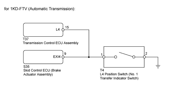
for 1KD-FTV (Automatic Transmission):
Disconnect the T37 transmission control ECU connector.
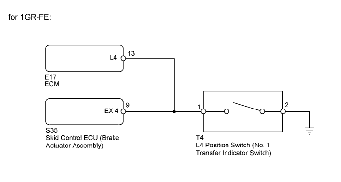
for 1GR-FE:
Disconnect the E17 ECM connector.
-
Disconnect the L4 position switch (No. 1 transfer indicator switch) connector.
-
Measure the resistance according to the value(s) in the table below.
Standard Resistance Tester Connection Condition Specified Condition S35-9 (EXI4) - T4-1 Always Below 1 Ω S35-9 (EXI4) - Body ground Always 10 kΩ or higher T4-2 - Body ground Always Below 1 Ω
NG
REPAIR OR REPLACE HARNESS OR CONNECTOR
OK
-
-
INSPECT L4 POSITION SWITCH
-
Turn the ignition switch off.
-
Remove the L4 position switch (No. 1 transfer indicator switch).
-
Inspect the L4 position switch (No. 1 transfer indicator switch) Click here.
NG
REPLACE NO. 1 TRANSFER INDICATOR SWITCH
OK
-
-
CHECK TERMINAL VOLTAGE (L4 POSITION SWITCH POWER SOURCE CIRCUIT)
-
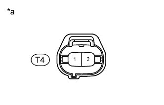
Text in Illustration *a Front view of wire harness connector
(to L4 Position Switch [No. 1 Transfer Indicator Switch])
Turn the ignition switch off.
-
Disconnect the L4 position switch (No. 1 transfer indicator switch) connector.
-
Disconnect the skid control ECU (brake actuator assembly) connector.
-
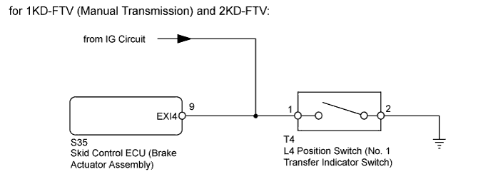
for 1KD-FTV (Automatic Transmission):
Connect the transmission control ECU connector.
for 1GR-FE:
Connect the ECM connector.
-
Measure the voltage according to the value(s) in the table below.
Standard Voltage Tester Connection Switch Condition Specified Condition 1 - 2 Ignition switch ON 11 to 14 V Result Result Proceed to OK A NG for 1KD-FTV (Manual Transmission) and 2KD-FTV B for 1KD-FTV (Automatic Transmission) C for 1GR-FE D
B
REPAIR OR REPLACE HARNESS OR CONNECTOR
C
CHECK HARNESS AND CONNECTOR (SKID CONTROL ECU - TRANSMISSION CONTROL ECU) Click here
D
CHECK HARNESS AND CONNECTOR (SKID CONTROL ECU - ECM) Click here
A
USE SIMULATION METHOD TO CHECK Click here
-
-
CHECK HARNESS AND CONNECTOR (SKID CONTROL ECU - TRANSMISSION CONTROL ECU)
-
Turn the ignition switch off.
-
Disconnect the skid control ECU (brake actuator assembly) connector.
-
Disconnect the T37 transmission control ECU connector.
-
Disconnect the L4 position switch (No. 1 transfer indicator switch) connector.
-
Measure the resistance according to the value(s) in the table below.
Standard Resistance Tester Connection Condition Specified Condition S35-9 (EXI4) - T37-15 (L4) Always Below 1 Ω S35-9 (EXI4) - Body ground Always 10 kΩ or higher
NG
REPAIR OR REPLACE HARNESS OR CONNECTOR
OK
REPLACE TRANSMISSION CONTROL ECU ASSEMBLY
-
-
CHECK HARNESS AND CONNECTOR (SKID CONTROL ECU - ECM)
-
Turn the ignition switch off.
-
Disconnect the skid control ECU (brake actuator assembly) connector.
-
Disconnect the E17 ECM connector.
-
Disconnect the L4 position switch (No. 1 transfer indicator switch) connector.
-
Measure the resistance according to the value(s) in the table below.
Standard Resistance Tester Connection Condition Specified Condition S35-9 (EXI4) - E17-13 (L4) Always Below 1 Ω S35-9 (EXI4) - Body ground Always 10 kΩ or higher
NG
REPAIR OR REPLACE HARNESS OR CONNECTOR
OK
REPLACE ECM Click here
-