TELEMATICS SYSTEM(for ERA-GLONASS), Diagnostic DTC:B1572
| DTC Code | DTC Name |
|---|---|
| B1572 | Microphone Error |
DESCRIPTION
This DTC is stored when a microphone signal line is disconnected.
| DTC No. | Detection Item | DTC Detection Condition | Trouble Area |
|---|---|---|---|
| B1572 | Microphone Error | Current at terminal MCVD exceeds the malfunction threshold for 10 seconds or more while the engine switch is on (IG) |
|
WIRING DIAGRAM
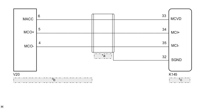
| *a | (Shielded) |
| *b | Roof Console Box Sub-assembly (Telephone Microphone Assembly) |
| *c | Telematics Transceiver |
CAUTION / NOTICE / HINT
Note
Depending on the parts that are replaced during vehicle inspection or maintenance, performing initialization, registration or calibration may be needed. Refer to Registration for Telematics System.
PROCEDURE
-
CHECK DTC
-
Turn the engine switch off.
-
Connect the GTS to the DLC3.
-
Turn the engine switch on (IG) and wait for 10 seconds or more.
-
Turn the GTS on.
-
Clear the DTCs.
Body Electrical > Telematics > Clear DTCs -
Check for DTCs and check that no DTCs are output.
Body Electrical > Telematics > Trouble CodesOK No DTCs are output. Result Proceed to OK NG
OK 
USE SIMULATION METHOD TO CHECK Click here
NG 
-
-
INSPECT TELEMATICS TRANSCEIVER
-
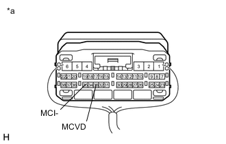
*a Component with harness connected
(Telematics Transceiver)
Measure the voltage and resistance according to the value(s) in the table below.
Standard Voltage Tester Connection Condition Specified Condition 33 (MCVD) - Body ground Engine switch on (ACC) 4 to 6 V Standard Resistance Tester Connection Condition Specified Condition 35 (MCI-) - Body ground Always Below 1 Ω Result Proceed to OK NG
NG 
REPLACE TELEMATICS TRANSCEIVER Click here
OK
-
-
CHECK HARNESS AND CONNECTOR (TELEMATICS TRANSCEIVER - ROOF CONSOLE BOX SUB-ASSEMBLY (TELEPHONE MICROPHONE ASSEMBLY))
-
Disconnect the K145 telematics transceiver connector.
-
Disconnect the V20 roof console box sub-assembly (telephone microphone assembly) connector.
-
Measure the resistance according to the value(s) in the table below.
Standard Resistance Tester Connection Condition Specified Condition K145-33 (MCVD) - V20-6 (MACC) Always Below 1 Ω K145-34 (MCI+) - V20-5 (MCO+) Always Below 1 Ω K145-35 (MCI-) - V20-4 (MCO-) Always Below 1 Ω K145-33 (MCVD) or V20-6 (MACC) - Body ground Always 10 kΩ or higher K145-34 (MCI+) or V20-5 (MCO+) - Body ground Always 10 kΩ or higher K145-35 (MCI-) or V20-4 (MCO-) - Body ground Always 10 kΩ or higher K145-32 (SGND) - Body ground Always 10 kΩ or higher Result Proceed to OK NG
NG
REPAIR OR REPLACE HARNESS OR CONNECTOR
OK
-
-
INSPECT ROOF CONSOLE BOX SUB-ASSEMBLY (TELEPHONE MICROPHONE ASSEMBLY)
-
Remove the roof console box sub-assembly (telephone microphone assembly).
-
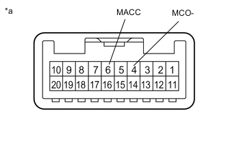
*a Component without harness connected
(Roof Console Box Sub-assembly (Telephone Microphone Assembly))
Measure the resistance according to the value(s) in the table below.
Standard Resistance Tester Connection Condition Specified Condition 6 (MACC) - 4 (MCO-) Always Below 1 Ω Result Proceed to OK NG
OK
GO TO STEP 6 Click here
NG
-
-
REPLACE TELEPHONE MICROPHONE ASSEMBLY
-
Replace the telephone microphone assembly with a new or known good one.
-
Clear the DTCs.
Body Electrical > Telematics > Clear DTCs -
Recheck for DTCs and check that no DTCs are output.
Body Electrical > Telematics > Trouble CodesOK No DTCs are output. Result Proceed to OK NG
OK
END
NG
REPLACE ROOF CONSOLE BOX SUB-ASSEMBLY (TELEPHONE MICROPHONE) Click here
-
-
REPLACE TELEMATICS TRANSCEIVER
-
Replace the telematics transceiver with a new one.
Result Proceed to NEXT
NEXT
PERFORM REGISTRATION Click here
-