ENGINE ASSEMBLY REMOVAL
-
DISCHARGE FUEL SYSTEM PRESSURE
CAUTION:
-
Do not disconnect any part of the fuel system until you have discharged the fuel system pressure.
-
Even after discharging the fuel pressure, place a cloth or equivalent over fittings as you separate them to reduce risk of fuel spray on yourself or in the engine compartment.
-
Disconnect the cable from the negative (-) battery terminal.
CAUTION:
Wait at least 90 seconds after disconnecting the cable from the negative (-) battery terminal to prevent airbag and seat belt pretensioner activation.
-
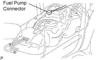
Disconnect the fuel pump connector.
-
Connect the cable to the negative (-) battery terminal.
-
Start the engine. After the engine has stopped on its own, turn the ignition switch OFF.
Tech Tips
DTC P0171/25 (system too lean) may be set.
-
Crank the engine again, then check that the engine does not start.
-
Loosen the fuel tank cap, then discharge the pressure in the fuel tank completely.
-
Connect the fuel pump connector.
-
-
DISCONNECT CABLE FROM NEGATIVE BATTERY TERMINAL
CAUTION:
Wait at least 90 seconds after disconnecting the cable from the negative (-) battery terminal to prevent airbag and seat belt pretensioner activation.
Note
When disconnecting the cable, systems need to be initialized after the cable is reconnected Click here.
-
DRAIN ENGINE COOLANT
-
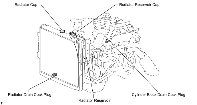
Remove the radiator cap.
-
Loosen the cylinder block drain cock plug and radiator drain plug, and then the coolant.
Tech Tips
Collect the coolant in a container and dispose of it according to the regulations in your area.
-
-
DRAIN ENGINE OIL
-
Remove the engine under cover.
-
Remove the oil pan drain plug and drain the engine oil into a container.
-
-
REMOVE BATTERY
-
REMOVE HOOD
-
Disconnect the washer nozzle hose.
-
Remove the 4 bolts and hood.
-
-
REMOVE V-BANK COVER
-
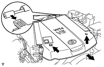
Remove the 2 nuts and the V-bank cover.
-
-
DISCONNECT NO. 2 VENTILATION HOSE
-
REMOVE AIR CLEANER
-
Disconnect the vacuum hose.
-
Disconnect the MAF meter connector.
-
Remove the 2 wire harness clamps.
-
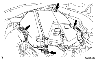
Loosen the 2 hose clamps.
-
Remove the 2 bolts and air cleaner.
-
-
REMOVE RADIATOR GRILLE
-
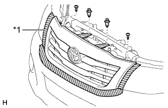
Text in Illustration *1 Protective Tape Put protective tape around the radiator grille.
-
Remove the 2 clips and 2 screws.
-
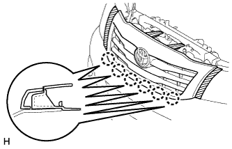
Detach the 6 claws and remove the radiator grille.
-
-
REMOVE RADIATOR SIDE DEFLECTOR RH
-
Using a clip remover, remove the 2 clips.
-
Detach the claw and remove the deflector.
-
-
REMOVE RADIATOR SIDE DEFLECTOR LH
-
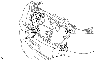
Using a clip remover, remove the 2 clips.
-
Detach the claw and remove the deflector.
-
-
REMOVE FAN SHROUD
-
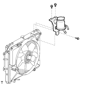
Remove the 3 bolts and oil reservoir.
-
Disconnect the reservoir hose from the radiator tank upper.
-
Loosen the 4 nuts holding the fluid coupling fan.
-
Remove the drive belt Click here.
-
Remove the 2 bolts holding the fan shroud.
-
Remove the 4 nuts of the fluid coupling fan, and then remove the shroud together with the fluid coupling fan.
Note
Be careful not to damage the radiator core.
-
Remove the fan pulley from the water pump.
-
-
LOOSEN FAN WITH FLUID COUPLING
-
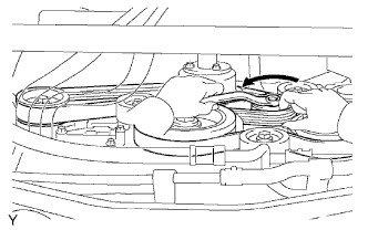
REMOVE DRIVE BELT
-
While releasing the belt tension by turning the belt tensioner counterclockwise, remove the V-ribbed belt from the belt tensioner.
-
-
REMOVE FAN WITH FLUID COUPLING
-
Remove the 4 nuts and fan with fluid coupling.
-
-
REMOVE FAN PULLEY
-
REMOVE RADIATOR
-
Disconnect the 2 front airbag sensor connectors.
-
Using a clip remover, detach the 4 clamps from the radiator side as shown in the illustration.
Tech Tips
Tape the clip remover tip before use.
-
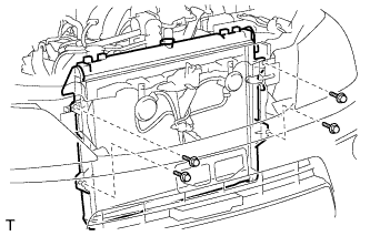
Remove the 4 bolts and radiator.
-
-
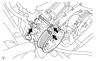
DISCONNECT VANE PUMP
-
Disconnect the oil pressure switch connector.
-
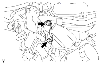
Remove the 2 bolts, and disconnect the vane pump.
Note
Do not hit other parts with the pulley when disconnecting the vane pump.
Tech Tips
Make sure to suspend the vane pump securely.
-
-
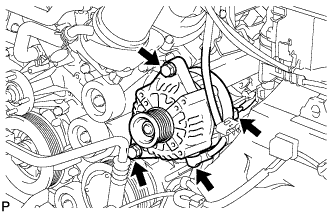
REMOVE GENERATOR
-
Remove the nut and generator wire.
-
Disconnect the generator connector.
-
Remove the 2 bolts and generator.
-
-
DISCONNECT COOLER COMPRESSOR
-
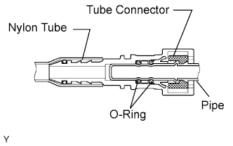
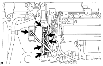
DISCONNECT NO. 1 FUEL PIPE
-
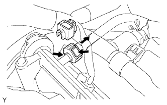
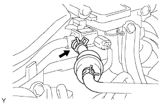
Remove the fuel pipe clamp.
-
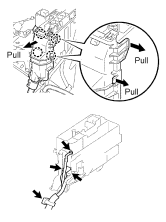
Pinch the tube connector and then pull out the fuel pipe.
Note
-
-
Check if there is any dirt or mud around the connector before this procedure, Clean if necessary. Foreign matter can affect the quick connector O-ring's seal between the fuel pipe and fuel delivery pipe.
-
Do not use any tool in this procedure.
-
Do not bend or twist the nylon tube.
-
Keep the plug free from foreign objects.
-
To protect the fuel pipe, cover it with a plastic bag after checking.
-
When the fuel pipe and fuel delivery pipe are stuck, pinch the nylon tube with your fingers, and turn it carefully to free and then disconnect the fuel pipe.
-
-
-
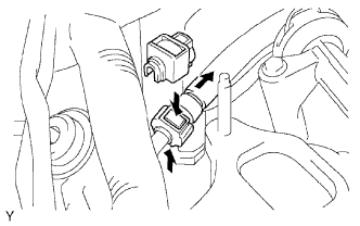
DISCONNECT NO. 2 FUEL PIPE
-
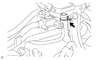
Remove the fuel pipe clamp.
-
Pinch the tube connector and then pull out the fuel pipe.
Note
-
-
Check if there is any dirt or mud around the connector before this procedure, Clean if necessary. Foreign matter can affect the quick connector O-ring's seal between the fuel pipe and fuel delivery pipe.
-
Do not use any tool in this procedure.
-
Do not bend or twist the nylon tube.
-
Keep the plug free from foreign objects.
-
To protect the fuel pipe, cover it with a plastic bag after checking.
-
When the fuel pipe and fuel pressure regulator are stuck, pinch the nylon tube with fingers, and turn it carefully to free and then disconnect the fuel pipe.
-
-
-
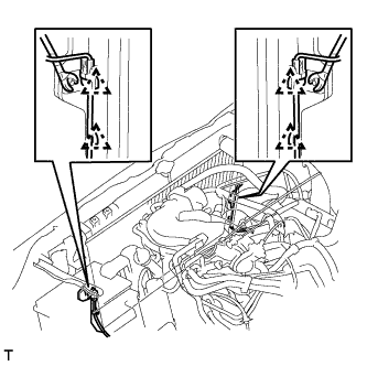
DISCONNECT HEATER HOSE
-
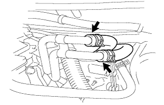
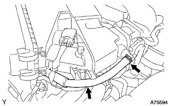
Disconnect the heater water inlet hoses.
-
Disconnect the heater water outlet hose.
-
-
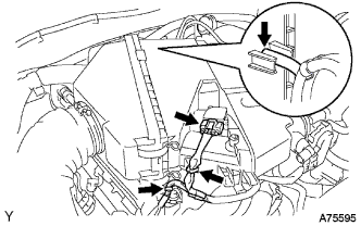
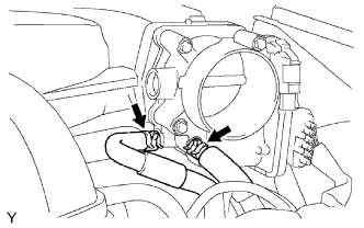
REMOVE INTAKE AIR SURGE TANK
-
Disconnect the 2 water by-pass hoses.
-
Disconnect the purge line hose.
-
Disconnect the ventilation hose.
-
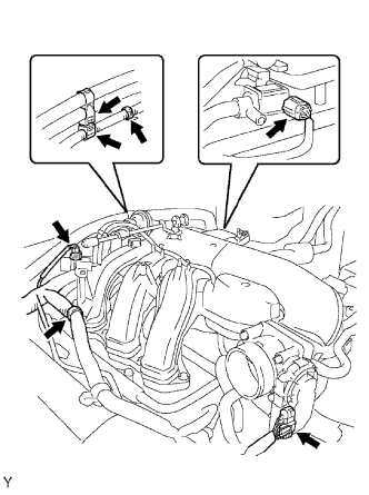
Disconnect the 2 VSV connectors.
-
Disconnect the throttle body with motor connector.
-
Separate the 3 wire harness clamps and hose clamp.
-
Remove the 2 bolts and throttle body bracket.
-
Remove the bolt and oil baffle plate.
-
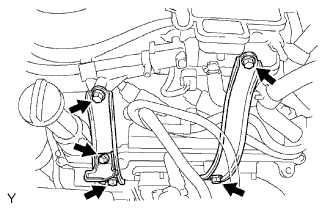
Remove the 4 bolts and 2 surge tank stays.
-
Remove the 2 nuts.
-
Using an 8 mm hexagon socket wrench, remove the 4 bolts, intake air surge tank and gasket.
-
-
DISCONNECT ENGINE WIRE
-
Disconnect the ECM connectors from the cabin:
-
Remove the glove compartment door.
-
Disconnect the 5 ECM connectors.
-
Disconnect the 4WD control ECU connector.
-
-
Remove the nut, and disconnect the ground wire.
-
Remove the bolt and disconnect the ground wire from the frame.
-
Pull the end of the engine wire into the engine compartment.
-
Remove the upper relay block cover.
-
Remove the side relay block cover.
-
Using a screwdriver, detach the 4 claws and remove the relay block cover.
Tech Tips
Tape the screwdriver tip before use.
-
-
Remove the nut and disconnect the cable from the engine room junction block.
-
Disconnect the 2 engine room junction block connectors and detach the wire clamp.
-
Remove the bolt and disconnect the wire clamp from the engine mounting bracket front LH.
-
Disconnect the 2 A/F sensor connectors.
-
Disconnect the A.D.D. connector.
-
-
DISCONNECT NO. 2 ENGINE WIRE
-
Disconnect the No. 2 engine wire from the cylinder block.
-
-
REMOVE FRONT EXHAUST PIPE
-
Remove the 2 nuts, pipe support and exhaust pipe.
-
-
REMOVE FRONT FENDER SEAL
-
Remove the front tires.
-
Remove the 10 clips and RH and LH fender seals.
-
-
REMOVE FRONT FENDER APRON SEAL UPPER
-
Remove the 10 clips and RH and LH fender apron seals.
-
-
REMOVE EXHAUST MANIFOLD RH
-
Remove the 6 nuts, exhaust manifold and gasket.
-
-
REMOVE EXHAUST MANIFOLD LH
-
Remove the 6 nuts, exhaust manifold and gasket.
-
-
REMOVE STARTER
-
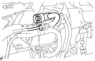
Disconnect the starter connector.
-
Remove the nut and disconnect the starter wire.
-
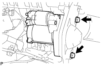
Remove the 2 bolts and starter.
-
-
REMOVE AUTOMATIC TRANSMISSION
-
4WD:
Remove the automatic transmission from the vehicle Click here.
-
2WD:
Remove the automatic transmission from the vehicle Click here.
-
-
REMOVE DRIVE PLATE AND RING GEAR
-
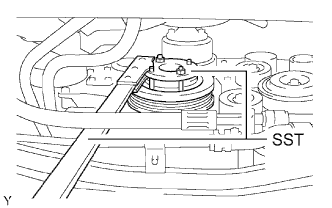
Using SST, hold the crankshaft.
- SST
- 09213-54015 ( 91651-60855 )
- 09330-00021
-
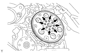
Remove the 8 bolts, rear spacer, drive plate and front spacer.
Note
Do not reuse the bolts.
-
-
REMOVE ENGINE ASSEMBLY
-
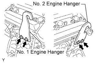
Install the 2 engine hangers with 4 bolts as shown in the illustration.
Engine hanger part No. Item Part No No. 1 engine hanger 12281-31060 No. 2 engine hanger 12282-31040 Bolt 90119-08A87 - Torque:
- 33 N*m { 336 kgf*cm, 24 ft.*lbf }
-
Attach the engine sling device and chain block to the engine hangers.
-
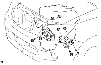
Remove the 4 bolts and 4 nuts holding the engine mounting brackets to the frame.
-
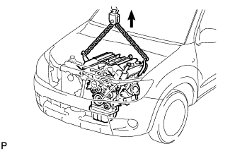
Lift the engine out of the vehicle carefully.
Note
Make sure all the wires, hoses and cables are disconnected from the engine. Keep the disconnected wires, hoses and cables off of the engine.
-
-
INSTALL ENGINE TO ENGINE STAND
-
Install the engine assembly to a stand.
-
-
REMOVE ENGINE WIRE FROM ENGINE ASSEMBLY
-
REMOVE NO. 1 RADIATOR HOSE
-
REMOVE NO. 2 RADIATOR HOSE
-
REMOVE HEATER WATER HOSE FROM ENGINE ASSEMBLY
-
REMOVE VENTILATION HOSE
-
REMOVE NO. 2 VENTILATION HOSE
-
REMOVE NO. 1 ENGINE MOUNTING BRACKET FRONT RH
-
Remove the 4 bolts and engine mounting bracket.
-
-
REMOVE NO. 1 ENGINE MOUNTING BRACKET FRONT LH
-
Remove the 3 bolts and engine mounting bracket.
-
-
REMOVE IDLER PULLEY (w/o Air Conditioning System)
-
Remove the 3 bolts and idler pulley.
-
-
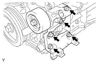
REMOVE V-RIBBED BELT TENSIONER
-
Remove the 5 bolts and V-ribbed belt tensioner.
-
-
REMOVE WATER INLET
-
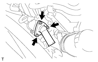
Remove the 3 nuts, water inlet with thermostat and gasket.
-
-
REMOVE OIL FILTER BRACKET
-
Remove the 3 bolts, 2 nuts, oil filter bracket and gasket.
-
-
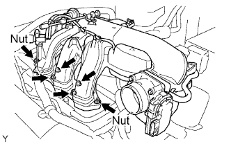
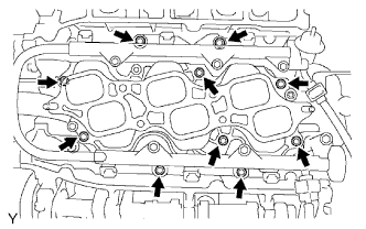
REMOVE INTAKE MANIFOLD
-
Disconnect the 6 fuel injector connectors.
-
Remove the 10 bolts, intake manifold and 2 gaskets.
-
-
REMOVE CAMSHAFT TIMING OIL CONTROL VALVE
-
Remove the 2 bolts and 2 camshaft timing oil control valves.
-
-
REMOVE WATER BY-PASS JOINT REAR
-
Disconnect the engine coolant temperature sensor connector.
-
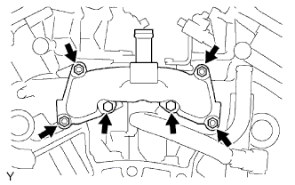
Remove the 2 bolts, 4 nuts, water by-pass joint and 2 gaskets.
-
Remove the O-ring from the water outlet pipe.
-
-
REMOVE OIL FILLER CAP
-
REMOVE OIL FILLER CAP HOUSING
-
Remove the 2 nuts, oil filler cap housing and gasket.
-
-
REMOVE IGNITION COIL
-
Remove the 6 bolts and 6 ignition coils.
-
-
REMOVE SPARK PLUG
-
REMOVE OIL DIPSTICK GUIDE
-
Remove the oil dipstick gauge.
-
Remove the bolt and pull out the oil dipstick gauge guide.
-
Remove the O-ring from the oil dipstick gauge guide.
-
-
REMOVE NO. 2 IDLER PULLEY
Note
Use the same procedure for both No. 2 idler pulleys.
-
w/ Idler Pulley Cover Plate:
-
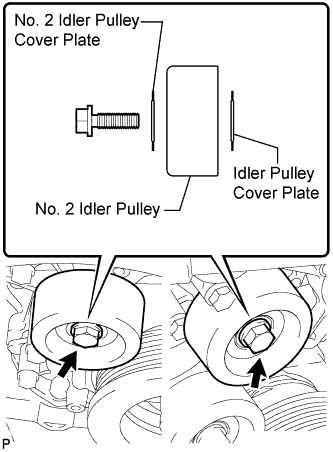
Remove the bolt, No. 2 idler pulley cover plate, idler pulley and idler pulley cover plate.
-
-
w/o Idler Pulley Cover Plate:
-
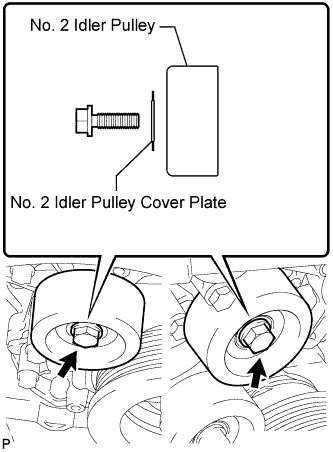
Remove the bolt, No. 2 idler pulley cover plate and idler pulley.
-
-
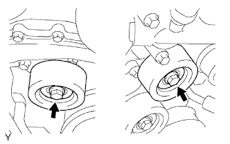
for Integrated Type:
Remove the 2 bolts and 2 No. 2 idler pulleys.
-
-
REMOVE NO. 1 IDLER PULLEY
-
Remove the bolt and idler pulley.
-