FRONT BUMPER REASSEMBLY
PROCEDURE
-
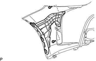
INSTALL FRONT SIDE MEMBER BRACKET SUB-ASSEMBLY LH
-
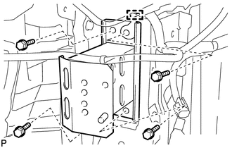
Engage the guide.
-
Install the front side member bracket sub-assembly LH with the 4 bolts.
- Torque:
- 50 N*m { 510 kgf*cm, 37 ft.*lbf }
-
-
INSTALL FRONT SIDE MEMBER BRACKET SUB-ASSEMBLY RH
Tech Tips
Use the same procedure as for the LH side.
-
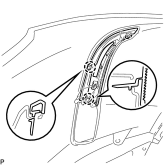
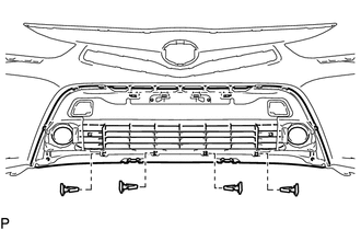
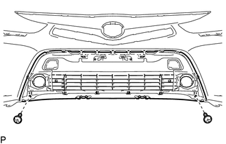
INSTALL FRONT BUMPER SIDE SUPPORT LH
-
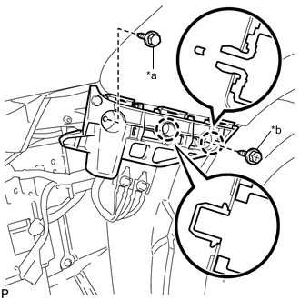
Text in Illustration *a Bolt *b Screw Engage the 2 claws.
-
Install the front bumper side support LH with the bolt and screw.
- Torque:
- Bolt
- 5.4 N*m { 55 kgf*cm, 48 in.*lbf }
- Screw
- 2.0 N*m { 20 kgf*cm, 18 in.*lbf }
-
-
INSTALL FRONT BUMPER SIDE SUPPORT RH
Tech Tips
Use the same procedure as for the LH side.
-
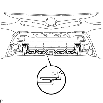
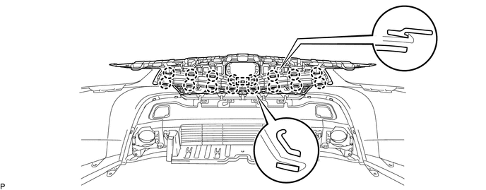
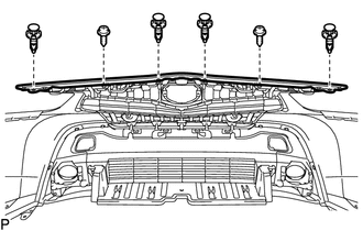
INSTALL FRONT BUMPER REINFORCEMENT SUB-ASSEMBLY
-
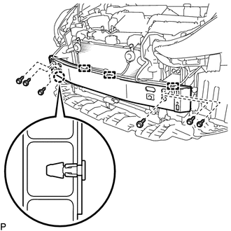
Engage the claw.
-
Install the front bumper reinforcement sub-assembly with the 6 bolts.
- Torque:
- 30 N*m { 306 kgf*cm, 22 ft.*lbf }
-
Engage the 3 clamps.
-
-
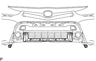
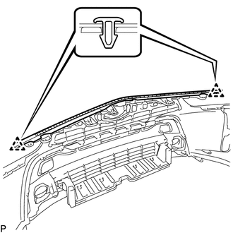
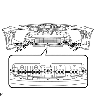
INSTALL FRONT BUMPER ENERGY ABSORBER
-
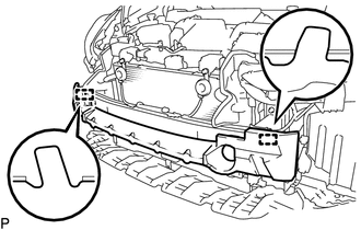
Engage the 2 guides to install the front bumper energy absorber.
-
-
INSTALL FRONT BUMPER EXTENSION LH
-
Engage the 2 claws to install the front bumper extension LH.
-
-
INSTALL FRONT BUMPER EXTENSION RH
Tech Tips
Use the same procedure as for the LH side.
-
INSTALL FRONT FENDER LINER RETAINER
-
Engage the claw to install the 3 front fender liner retainers.
Tech Tips
Use the same procedure for the RH side and LH side.
-
-
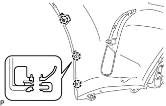
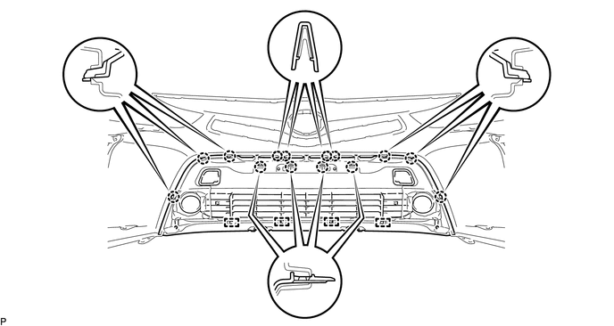
INSTALL AIR INTAKE DUCT LH
-
Install the 2 screws.
-
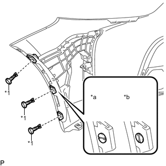
Text in Illustration *1 Pin Hold Clip *a Correct *b Incorrect Install the air intake duct LH with the 3 pin hold clips as shown in the illustration.
Note
Insert the pin hold clip with the slot aligned vertically. Do not rotate the clip after inserting it. After installation, confirm that the slot is aligned vertically.
-
-
INSTALL AIR INTAKE DUCT RH
Tech Tips
Use the same procedure for the RH side and LH side.
-
INSTALL FRONT BUMPER HOLE COVER LH
-
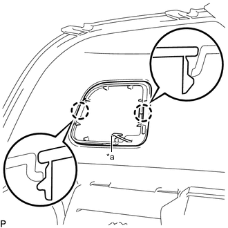
Text in Illustration *a Hook Engage the hook.
-
Engage the 2 claws and install the front bumper hole cover LH.
-
-
INSTALL FRONT BUMPER HOLE COVER RH
Tech Tips
Use the same procedure as for the LH side.
-
INSTALL LOWER RADIATOR GRILLE SUB-ASSEMBLY
-
Engage the 4 guides and 14 claws.
-
Install the 4 outside moulding retainers.
-
Install the lower radiator grille sub-assembly with the 2 screws.
-
-
INSTALL LOWER NO. 2 RADIATOR GRILLE
-
Engage the 6 claws.
-
Install the lower No. 2 radiator grille with the 2 screws.
-
-
INSTALL FRONT BUMPER EMBLEM SUB-ASSEMBLY
-
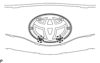
Engage the 2 claws.
-
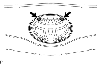
Install the front bumper emblem sub-assembly with the 2 screws.
-
-
INSTALL RADIATOR GRILLE
-
Engage the guide and 16 claws.
-
Install the 4 clips.
-
Install the radiator grille with the 2 screws.
-
-
INSTALL HOOD TO FRONT END PANEL SEAL
-
Clean the front bumper cover.
-
Remove any remaining double-sided tape from the front bumper cover.
-
Wipe off any tape adhesive residue with cleaner.
-
-
Remove the release paper from a new hood to front end panel seal.
Tech Tips
After removing the release paper, keep the exposed adhesive free from foreign matter.
-
Install the hood to front end panel seal with 2 clips.
Text in Illustration 
Double-sided Tape
-
-
INSTALL FOG LIGHT ASSEMBLY LH
-
INSTALL FOG LIGHT ASSEMBLY RH
Tech Tips
Use the same procedure as for the LH side.
-
INSTALL NO. 3 ENGINE ROOM WIRE
-
Engage the 11 clamps to install the No. 3 engine room wire.
-
-
INSTALL DAYTIME RUNNING LIGHT ASSEMBLY LH
-
INSTALL DAYTIME RUNNING LIGHT ASSEMBLY RH
Tech Tips
Use the same procedure as for the LH side.
-
INSTALL NO. 1 ULTRASONIC SENSOR RETAINER (w/ Intelligent Parking Assist System)
-
INSTALL NO. 1 ULTRASONIC SENSOR (w/ Intelligent Parking Assist System)
-
INSTALL MILLIMETER WAVE RADAR SENSOR ASSEMBLY (w/ Pre-collision System)