FUEL TANK INSTALLATION
PROCEDURE
INSTALL FUEL TANK TO FILLER PIPE HOSE
-
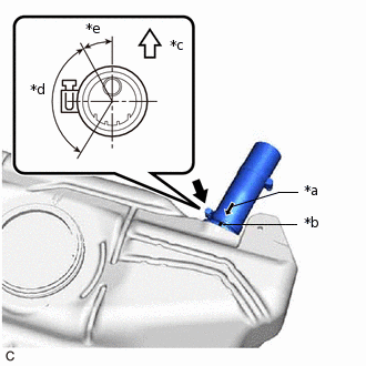
*a
Match Mark
*b
Protrusion
*c
Upper
*d
120°
*e
30°
Install the fuel tank to filler pipe hose to the fuel tank sub-assembly and tighten the clamp to secure it.
Tip:Make sure the clamp bolt is within the area shown in the illustration.
Align the match mark of the fuel tank to filler pipe hose with the protrusion of the fuel tank sub-assembly.
-
INSTALL NO. 1 FUEL EMISSION TUBE SUB-ASSEMBLY
Engage the 2 claws to install the No. 1 fuel emission tube sub-assembly to the fuel tank sub-assembly.
INSTALL FUEL TANK MAIN TUBE SUB-ASSEMBLY
Engage the 2 claws to install the fuel tank main tube sub-assembly to the fuel tank sub-assembly.
INSTALL FUEL TANK SUB-ASSEMBLY
Set the fuel tank sub-assembly on an engine lifter.
Tip:Using height adjustment attachments and plate lift attachments, place the fuel tank sub-assembly horizontally.
Using the engine lifter, slowly raise the fuel tank sub-assembly, and then install the fuel tank sub-assembly with 4 new bolts.
Note:Do not drop the fuel tank sub-assembly.
When installing the fuel tank sub-assembly, tilt it slightly to prevent it from interfering with the suspension arm or other surrounding parts.
14.3 N*m
146 kgf*cm
11 ft.*lbf
INSTALL CENTER LOWER FUEL TANK PROTECTOR
Using a T20 "TORX" socket wrench, install the center lower fuel tank protector to the fuel tank sub-assembly with the 3 "TORX" screws.
INSTALL PARKING BRAKE CABLE ASSEMBLY
Install the No. 2 parking brake cable assembly and No. 3 parking brake cable assembly with the 2 bolts.
6.0 N*m
61 kgf*cm
53 in.*lbf
INSTALL FUEL TANK FILLER PIPE SUB-ASSEMBLY
Install the fuel tank filler pipe sub-assembly to the fuel tank to filler pipe hose and tighten the clamp to secure it.
Install the bolt.
10 N*m
102 kgf*cm
7 ft.*lbf
Install the fuel tank cap assembly.
CONNECT NO. 1 FUEL EMISSION TUBE SUB-ASSEMBLY
Note:Check if there is any damage or foreign matter on the connecting parts of the fuel lines.
-
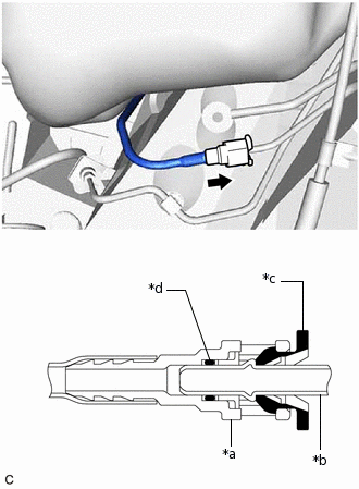
*a
Fuel Tube Connector
*b
Fuel Pipe
*c
Retainer
*d
O-ring

Push
Connect the No. 1 fuel emission tube sub-assembly.
Align the fuel tube connector with the fuel pipe, and push them together until the fuel tube connector makes a "click" sound. If it is difficult to push the fuel pipe into the fuel tube connector, apply a small amount of clean engine oil to the tip of the fuel pipe and reinsert it.
After connecting the fuel lines, check that the fuel pipe and fuel tube connector are securely connected by pulling on them.
-
CONNECT FUEL TANK MAIN TUBE SUB-ASSEMBLY
Note:Check if there is any damage or foreign matter on the connecting parts of the fuel lines.
-
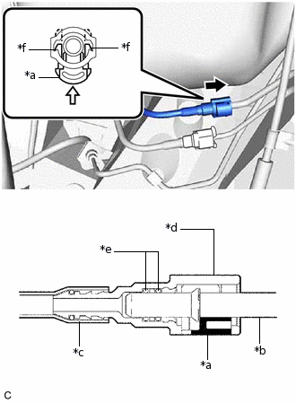
*a
Retainer
*b
Fuel Pipe
*c
Nylon Tube
*d
Fuel Tube Connector
*e
O-ring
*f
Claw
Push

Push in
Connect the fuel tank main tube sub-assembly.
Align the fuel tube connector with the fuel pipe, and push them together until the fuel tube connector makes a "click" sound. If it is difficult to push the fuel pipe into the fuel tube connector, apply a small amount of clean engine oil to the tip of the fuel pipe and reinsert it.
Connect the fuel lines and push in the retainer to engage the 2 claws. Check that the fuel pipe and fuel tube connector are securely connected by pulling on them.
-
INSTALL FRONT EXHAUST PIPE ASSEMBLY
INSTALL FUEL SUCTION TUBE WITH PUMP AND GAUGE ASSEMBLY
ADD FUEL