СИСТЕМА ЗАПУСКА И ОСТАНОВА (для моделей с 2AR-FE) STA Signal Circuit
DESCRIPTION
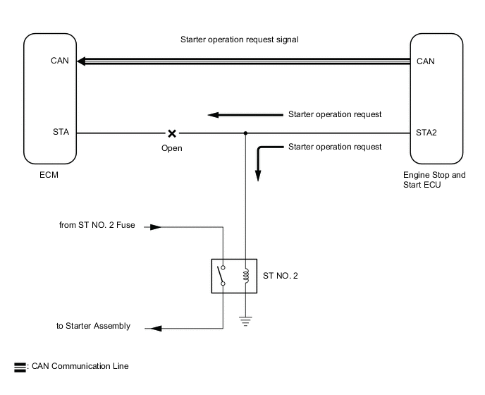
While the engine is being cranked, a starter operation request signal is sent to terminal STA of the ECM.
Tech Tips
If there is an open in the STA circuit of the ECM, stop and start control will be prohibited after the third time the engine is started by stop and start control.
-
Stop and start control will be prohibited until the engine switch is turned off.
-
The MIL will not illuminate.
-
If there is an open in the STA circuit of the ECM, the engine can still be started using the engine switch, as the ECM also receives the starter operation request signal from the engine stop and start ECU via CAN communication. (Stop and start control is prohibited as the reliability of the signal sent via CAN communication cannot be assured while the voltage drops during operation of the starter assembly.)
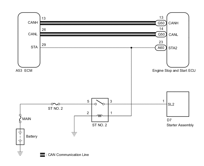
WIRING DIAGRAM
PROCEDURE
-
READ VALUE USING GTS (STARTER SIGNAL)
-
Connect the GTS to the DLC3.
-
Turn the engine switch on (IG).
-
Turn the GTS on.
-
Enter the following menus: Powertrain / Engine and ECT / Data List / Starter Signal.
Powertrain > Engine and ECT > Data ListTester Display Starter Signal -
Read the values displayed on the GTS when the engine switch is on (ON) and on (START).
OK GTS Display Condition Normal Condition Starter Signal Engine switch on (ON) OFF Engine switch on (START) ON Result Proceed to OK NG
OK 
PROCEED TO NEXT SUSPECTED AREA SHOWN IN PROBLEM SYMPTOMS TABLE Click here
NG 
-
-
CHECK HARNESS AND CONNECTOR (ECM - ST NO. 2 RELAY)
-
Disconnect the ECM connector.
-
Remove the ST NO. 2 relay from the No. 1 engine room relay block.
-
Measure the resistance according to the value(s) in the table below.
Standard Resistance Tester Connection Condition Specified Condition A53-29 (STA) - 1 (ST NO. 2 relay) Always Below 1 Ω Result Proceed to OK NG
OK
PROCEED TO NEXT SUSPECTED AREA SHOWN IN PROBLEM SYMPTOMS TABLE Click here
NG
REPAIR OR REPLACE HARNESS OR CONNECTOR
-