LIGHTING SYSTEM Headlight (HI-BEAM) Circuit
DESCRIPTION
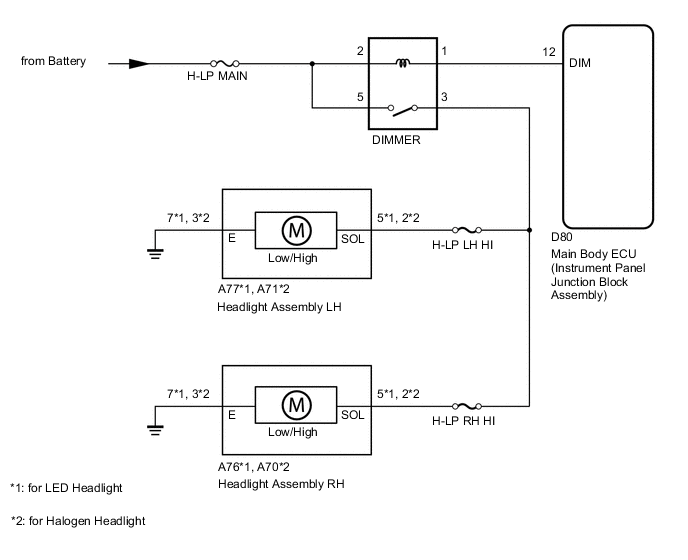
The main body ECU (instrument panel junction block assembly) receives light control switch and dimmer switch information signals from the headlight dimmer switch, and illuminates the high beam headlight.
WIRING DIAGRAM
CAUTION / NOTICE / HINT
Note
As the door control battery is installed between the vehicle battery and main body ECU (instrument panel junction block assembly), first perform the inspections in On-Vehicle Inspection to confirm that there are no malfunctions in the power source circuit for the main body ECU (instrument panel junction block assembly) before performing this troubleshooting procedure.
Tech Tips
Inspect the fuses and bulbs for circuits related to this system before performing the following inspection procedure.
PROCEDURE
-
PERFORM ACTIVE TEST USING GTS (HEAD LIGHT HI)
-
Connect the GTS to the DLC3.
-
Turn the ignition switch to ON.
-
Turn the GTS on.
-
Enter the following menus: Body Electrical / Main Body / Active Test / Head Light Hi.
-
Check that the headlight (high) turns on/off.
Main Body Tester Display Test Part Control Range Diagnostic Note Head Light Hi Headlight (High) ON or OFF - Tech Tips
Perform the inspection with the low beam headlights turned on.
OK Headlight (high) turns on/off.
OK 
PROCEED TO NEXT SUSPECTED AREA SHOWN IN PROBLEM SYMPTOMS TABLE Click here
NG 
-
-
CHECK HARNESS AND CONNECTOR (HEADLIGHT ASSEMBLY [HIGH] - HEADLIGHT DIMMER RELAY)
-
*1: for LH
-
*2: for RH
-
for LED Headlight:
-
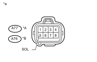
Text in Illustration *A for LH *B for RH *a Front view of wire harness connector
(to Headlight Assembly [High])
Disconnect the A77*1 or A76*2 headlight assembly (high) connector.
-
Measure the voltage according to the value(s) in the table below.
Standard Voltage for LH Tester Connection Switch Condition Specified Condition A77-5 (SOL) - Body ground Light control switch HEAD, dimmer switch high 11 to 14 V Light control switch HEAD, dimmer switch not high Below 1 V for RH Tester Connection Switch Condition Specified Condition A76-5 (SOL) - Body ground Light control switch HEAD, dimmer switch high 11 to 14 V Light control switch HEAD, dimmer switch not high Below 1 V
-
-
for Halogen Headlight:
-
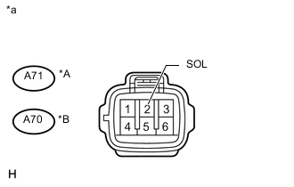
Text in Illustration *A for LH *B for RH *a Front view of wire harness connector
(to Headlight Assembly [High])
Disconnect the A71*1 or A70*2 headlight assembly (high) connector.
-
Measure the voltage according to the value(s) in the table below.
Standard Voltage for LH Tester Connection Switch Condition Specified Condition A71-2 (SOL) - Body ground Light control switch HEAD, dimmer switch high 11 to 14 V Light control switch HEAD, dimmer switch not high Below 1 V for RH Tester Connection Switch Condition Specified Condition A70-2 (SOL) - Body ground Light control switch HEAD, dimmer switch high 11 to 14 V Light control switch HEAD, dimmer switch not high Below 1 V
-
NG 
INSPECT DIMMER RELAY Click here
OK
-
-
CHECK HARNESS AND CONNECTOR (HEADLIGHT [HIGH] - BODY GROUND)
-
*1: for LH
-
*2: for RH
-
for LED Headlight:
-
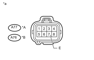
Text in Illustration *A for LH *B for RH *a Front view of wire harness connector
(to Headlight Assembly [High])
Disconnect the A77*1 or A76*2 headlight (high) connector.
-
Measure the resistance according to the value(s) in the table below.
Standard Resistance for LH Tester Connection Condition Specified Condition A77-7 (E) - Body ground Always Below 1 Ω for RH Tester Connection Condition Specified Condition A76-7 (E) - Body ground Always Below 1 Ω
-
-
for Halogen Headlight:
-
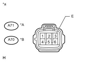
Text in Illustration *A for LH *B for RH *a Front view of wire harness connector
(to Headlight Assembly [High])
Disconnect the A71*1 or A70*2 headlight (high) connector.
-
Measure the resistance according to the value(s) in the table below.
Standard Resistance for LH Tester Connection Condition Specified Condition A71-3 (E) - Body ground Always Below 1 Ω for RH Tester Connection Condition Specified Condition A70-3 (E) - Body ground Always Below 1 Ω
Result Result Proceed to OK (for LED Headlight) A OK (for Halogen Headlight) B NG C -
A
REPLACE HEADLIGHT ASSEMBLY Click here
B
REPLACE HEADLIGHT ASSEMBLY Click here
C
REPAIR OR REPLACE HARNESS OR CONNECTOR
-
-
INSPECT DIMMER RELAY
-
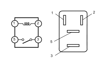
Remove the DIMMER relay from the engine room No. 1 relay block.
-
Measure the resistance according to the value(s) in the table below.
Standard Resistance Tester Connection Condition Specified Condition 3 - 5 Battery voltage not applied to terminals 1 and 2 10 kΩ or higher Battery voltage applied to terminals 1 and 2 Below 1 Ω
NG
REPLACE DIMMER RELAY
OK
-
-
CHECK HARNESS AND CONNECTOR (DIMMER RELAY - BATTERY)
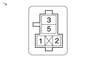
Text in Illustration *a Front view of wire harness connector
(to DIMMER Relay)
-
Remove the DIMMER relay from the engine room No. 1 relay block.
-
Measure the voltage according to the value(s) in the table below.
Standard Voltage Tester Connection Condition Specified Condition DIMMER relay terminal 2 - Body ground Always 11 to 14 V DIMMER relay terminal 5 - Body ground Always 11 to 14 V
NG
REPAIR OR REPLACE HARNESS OR CONNECTOR
OK
-
-
CHECK HARNESS AND CONNECTOR (DIMMER RELAY - HEADLIGHT ASSEMBLY [HIGH])
-
*1: for LH
-
*2: for RH
-
Remove the DIMMER relay from the engine room No. 1 relay block.
-
for LED Headlight:
-
Disconnect the A77*1 or A76*2 headlight assembly (high) connector.
-
Measure the resistance according to the value(s) in the table below.
Standard Resistance for LH Tester Connection Condition Specified Condition DIMMER relay terminal 3 - A77-5 (SOL) Always Below 1 Ω DIMMER relay terminal 3 - Body ground Always 10 kΩ or higher for RH Tester Connection Condition Specified Condition DIMMER relay terminal 3 - A76-5 (SOL) Always Below 1 Ω DIMMER relay terminal 3 - Body ground Always 10 kΩ or higher
-
-
for Halogen Headlight:
-
Disconnect the A71*1 or A70*2 headlight assembly (high) connector.
-
Measure the resistance according to the value(s) in the table below.
Standard Resistance for LH Tester Connection Condition Specified Condition DIMMER relay terminal 3 - A71-2 (SOL) Always Below 1 Ω DIMMER relay terminal 3 - Body ground Always 10 kΩ or higher for RH Tester Connection Condition Specified Condition DIMMER relay terminal 3 - A70-2 (SOL) Always Below 1 Ω DIMMER relay terminal 3 - Body ground Always 10 kΩ or higher
-
NG
REPAIR OR REPLACE HARNESS OR CONNECTOR
OK
-
-
CHECK HARNESS AND CONNECTOR (HEADLIGHT DIMMER RELAY - MAIN BODY ECU [INSTRUMENT PANEL JUNCTION BLOCK ASSEMBLY])
-
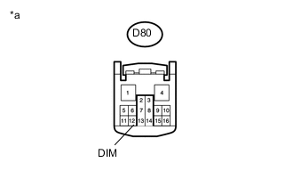
Text in Illustration *a Front view of wire harness connector
(to Main Body ECU [Instrument Panel Junction Block Assembly])
Disconnect the main body ECU (instrument panel junction block assembly) connector.
-
Measure the voltage according to the value(s) in the table below.
Standard Voltage Tester Connection Condition Specified Condition D80-12 (DIM) - Body ground Always 11 to 14 V
OK
REPLACE MAIN BODY ECU (INSTRUMENT PANEL JUNCTION BLOCK ASSEMBLY)
NG
REPAIR OR REPLACE HARNESS OR CONNECTOR
-