THEFT DETERRENT SYSTEM Horn Circuit
DESCRIPTION
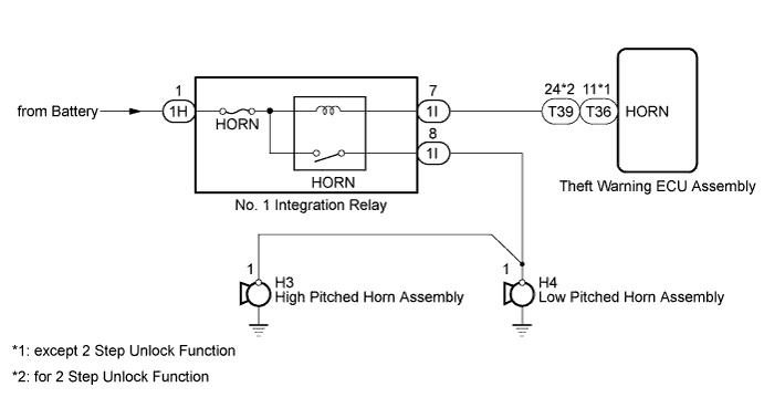
When the theft deterrent system is changed from the armed state to the alarm sounding state, the theft warning ECU assembly turns on the HORN relay, causing the vehicle horn to sound at 0.4 seconds intervals.
WIRING DIAGRAM
INSPECTION PROCEDURE
Note
When replacing the theft warning ECU assembly, refer to the registration procedures Click here.
PROCEDURE
-
CHECK HORN ASSEMBLY
-
Press the horn switch and check if the horn sounds.
Result Result Proceed to Horn sounds A Horn does not sound B
B 
Go to HORN SYSTEM Click here
A 
-
-
CHECK HARNESS AND CONNECTOR (THEFT WARNING ECU - NO. 1 INTEGRATION RELAY [HORN RELAY])
-
Disconnect the T36*1 or T39*2 theft warning ECU assembly connector.
-
*1: except 2 Step Unlock Function
-
*2: for 2 Step Unlock Function
-
-
Disconnect the 1I driver side junction block assembly connector.
-
Measure the resistance according to the value in the table below.
Standard Resistance except 2 Step Unlock Function Tester Connection Condition Specified Condition T36-11 (HORN) - 1I-7 Always Below 1 Ω T36-11 (HORN) or 1I-7 - Body ground Always 10 kΩ or higher for 2 Step Unlock Function Tester Connection Condition Specified Condition T39-24 (HORN) - 1I-7 Always Below 1 Ω T39-24 (HORN) or 1I-7 - Body ground Always 10 kΩ or higher
NG
REPAIR OR REPLACE HARNESS OR CONNECTOR
OK 
REPLACE THEFT WARNING ECU ASSEMBLY
-