SFI SYSTEM Fuel Injector Circuit
| DTC Code | DTC Name |
|---|---|
| Fuel Injector Circuit |
DESCRIPTION
The Fuel injectors are installed in the intake port, and inject fuel into the cylinders based on the signals from the ECM.
WIRING DIAGRAM
Refer to DTC P0201.
CAUTION / NOTICE / HINT
After replacing the ECM, perform idle learning.
Inspect the fuses for circuits related to this system before performing the following procedure.
PROCEDURE
CHECK TERMINAL VOLTAGE (POWER SOURCE OF FUEL INJECTOR ASSEMBLY)
-
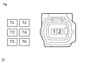
*a
Front view of wire harness connector
(to Fuel Injector Assembly)
Disconnect the fuel injector assembly connector.
Turn the ignition switch to ON.
Measure the voltage according to the value(s) in the table below.
Standard Voltage
Tester Connection
Condition
Specified Condition
T1-1 - Body ground
Ignition switch ON
11 to 14 V
T2-1 - Body ground
Ignition switch ON
11 to 14 V
T3-1 - Body ground
Ignition switch ON
11 to 14 V
T4-1 - Body ground
Ignition switch ON
11 to 14 V
T5-1 - Body ground
Ignition switch ON
11 to 14 V
T6-1 - Body ground
Ignition switch ON
11 to 14 V
Tip:The vehicle wire harness connector that connects to the fuel injector assembly can be connected to either of the 2 fuel injector assemblies of the same cylinder.
Result
Proceed to
OK
NG
NG CHECK HARNESS AND CONNECTOR (DRIVER SIDE JUNCTION BLOCK ASSEMBLY - FUEL INJECTOR ASSEMBLY)Click here
-
INSPECT FUEL INJECTOR ASSEMBLY (INJECTION AND VOLUME)
Inspect the fuel injector assembly injection and volume.
Result
Proceed to
OK
NG
CHECK HARNESS AND CONNECTOR (FUEL INJECTOR ASSEMBLY - ECM)
Disconnect the fuel injector assembly connector.
Disconnect the ECM connector.
Measure the resistance according to the value(s) in the table below.
Standard Resistance
Tester Connection
Condition
Specified Condition
T1-2 - B31-102 (#1)
Always
Below 1 Ω
T4-2 - B31-131 (#4)
Always
Below 1 Ω
T2-2 - B31-133 (#2)
Always
Below 1 Ω
T5-2 - B31-100 (#5)
Always
Below 1 Ω
T3-2 - B31-101 (#3)
Always
Below 1 Ω
T6-2 - B31-132 (#6)
Always
Below 1 Ω
T1-2 or B31-102 (#1) - Body ground
Always
10 kΩ or higher
T4-2 or B31-131 (#4) - Body ground
Always
10 kΩ or higher
T2-2 or B31-133 (#2) - Body ground
Always
10 kΩ or higher
T5-2 or B31-100 (#5) - Body ground
Always
10 kΩ or higher
T3-2 or B31-101 (#3) - Body ground
Always
10 kΩ or higher
T6-2 or B31-132 (#6) - Body ground
Always
10 kΩ or higher
Tip:According to the connection condition of the vehicle wire harness connector that connects to the fuel injector assembly, check that there is continuity between either of the terminal pairs.
The vehicle wire harness connector that connects to the fuel injector assembly can be connected to either of the 2 fuel injector assemblies of the same cylinder.
Result
Proceed to
OK
NG
NG REPAIR OR REPLACE HARNESS OR CONNECTOR
CHECK HARNESS AND CONNECTOR (DRIVER SIDE JUNCTION BLOCK ASSEMBLY - FUEL INJECTOR ASSEMBLY)
Disconnect the driver side junction block assembly connector.
Disconnect the fuel injector assembly connector.
Measure the resistance according to the value(s) in the table below.
Standard Resistance
Tester Connection
Condition
Specified Condition
3C-2 - T1-1
Always
Below 1 Ω
3C-2 - T4-1
Always
Below 1 Ω
3C-2 - T2-1
Always
Below 1 Ω
3C-2 - T5-1
Always
Below 1 Ω
3C-2 - T3-1
Always
Below 1 Ω
3C-2 - T6-1
Always
Below 1 Ω
3C-2 or T1-1 - Body ground
Always
10 kΩ or higher
3C-2 or T4-1 - Body ground
Always
10 kΩ or higher
3C-2 or T2-1 - Body ground
Always
10 kΩ or higher
3C-2 or T5-1 - Body ground
Always
10 kΩ or higher
3C-2 or T3-1 - Body ground
Always
10 kΩ or higher
3C-2 or T6-1 - Body ground
Always
10 kΩ or higher
Tip:The vehicle wire harness connector that connects to the fuel injector assembly can be connected to either of the 2 fuel injector assemblies of the same cylinder.
Result
Proceed to
OK
NG
NG REPAIR OR REPLACE HARNESS OR CONNECTOR