SFI SYSTEM, Diagnostic DTC:P0201,P0202,P0203,P21CF,P21D0 and P21D1
| DTC Code | DTC Name |
|---|---|
| P0201 | Injector Circuit / Open - (Cylinder 1) |
| P0202 | Injector Circuit / Open - (Cylinder 2) |
| P0203 | Injector Circuit / Open - (Cylinder 3) |
| P21CF | Cylinder 1 Injector "B" Circuit/Open |
| P21D0 | Cylinder 2 Injector "B" Circuit/Open |
| P21D1 | Cylinder 3 Injector "B" Circuit/Open |
DESCRIPTION
The fuel injector assemblies are installed to the intake manifold, and perform fuel injection in response to signals from the ECM. If there is a malfunction in a fuel injector assembly circuit, a DTC is stored.
DTC No. |
Detection Item |
DTC Detection Condition |
Trouble Area |
MIL |
Memory |
|---|---|---|---|---|---|
P0201 |
Injector Circuit / Open - (Cylinder 1) |
Following conditions are met for 3 seconds (1 trip detection logic):
|
|
Comes on |
DTC stored |
P0202 |
Injector Circuit / Open - (Cylinder 2) |
Following conditions are met for 3 seconds (1 trip detection logic):
|
|
Comes on |
DTC stored |
P0203 |
Injector Circuit / Open - (Cylinder 3) |
Following conditions are met for 3 seconds (1 trip detection logic):
|
|
Comes on |
DTC stored |
P21CF |
Cylinder 1 Injector "B" Circuit/Open |
Following conditions are met for 3 seconds (1 trip detection logic):
|
|
Comes on |
DTC stored |
P21D0 |
Cylinder 2 Injector "B" Circuit/Open |
Following conditions are met for 3 seconds (1 trip detection logic):
|
|
Comes on |
DTC stored |
P21D1 |
Cylinder 3 Injector "B" Circuit/Open |
Following conditions are met for 3 seconds (1 trip detection logic):
|
|
Comes on |
DTC stored |
WIRING DIAGRAM
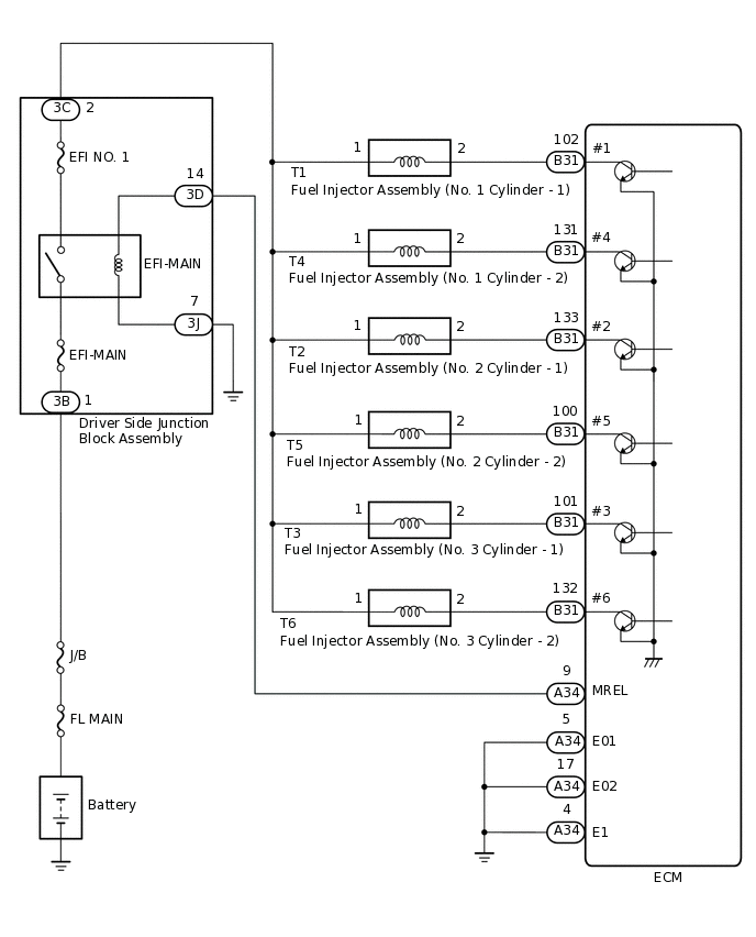
CAUTION / NOTICE / HINT
After replacing the ECM, perform idle learning.
Inspect the fuses for circuits related to this system before performing the following inspection procedure.
If P0201 or P21CF are output, inspect both the fuel injector circuit (No. 1 cylinder - 1) and fuel injector circuit (No. 1 cylinder - 2).
If P0202 or P21D0 are output, inspect both the fuel injector circuit (No. 2 cylinder - 1) and fuel injector circuit (No. 2 cylinder - 2).
If P0203 or P21D1 are output, inspect both the fuel injector circuit (No. 3 cylinder - 1) and fuel injector circuit (No. 3 cylinder - 2).
Read freeze frame data using the GTS. The ECM records vehicle and driving condition information as freeze frame data the moment a DTC is stored. When troubleshooting, freeze frame data can help determine if the vehicle was moving or stationary, if the engine was warmed up or not, if the air-fuel ratio was lean or rich, and other data from the time the malfunction occurred.
PROCEDURE
CHECK TERMINAL VOLTAGE (POWER SOURCE OF FUEL INJECTOR ASSEMBLY)
Disconnect the fuel injector assembly connector.
-
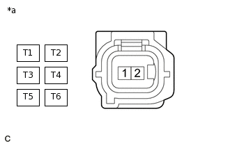
*a
Front view of wire harness connector
(to Fuel Injector Assembly)
Turn the ignition switch to ON.
Measure the voltage according to the value(s) in the table below.
Standard Voltage
Tester Connection
Condition
Specified Condition
T1-1 - Body ground
Ignition switch ON
11 to 14 V
T2-1 - Body ground
Ignition switch ON
11 to 14 V
T3-1 - Body ground
Ignition switch ON
11 to 14 V
T4-1 - Body ground
Ignition switch ON
11 to 14 V
T5-1 - Body ground
Ignition switch ON
11 to 14 V
T6-1 - Body ground
Ignition switch ON
11 to 14 V
Tip:The vehicle wire harness connector that connects to the fuel injector assembly can be connected to either of the 2 fuel injector assemblies of the same cylinder.
Result
Proceed to
OK
NG
NG CHECK HARNESS AND CONNECTOR (DRIVER SIDE JUNCTION BLOCK ASSEMBLY - FUEL INJECTOR ASSEMBLY)Click here
INSPECT FUEL INJECTOR ASSEMBLY
Check the fuel injector injection and volume.
Result
Proceed to
OK
NG
CHECK HARNESS AND CONNECTOR (FUEL INJECTOR ASSEMBLY - ECM)
Disconnect the fuel injector assembly connector.
Disconnect the ECM connector.
Measure the resistance according to the value(s) in the table below.
Standard Resistance
Tester Connection
Condition
Specified Condition
T1-2 - B31-102 (#1)
Always
Below 1 Ω
T4-2 - B31-131 (#4)
Always
Below 1 Ω
T2-2 - B31-133 (#2)
Always
Below 1 Ω
T5-2 - B31-100 (#5)
Always
Below 1 Ω
T3-2 - B31-101 (#3)
Always
Below 1 Ω
T6-2 - B31-132 (#6)
Always
Below 1 Ω
T1-2 or B31-102 (#1) - Body ground
Always
10 kΩ or higher
T4-2 or B31-131 (#4) - Body ground
Always
10 kΩ or higher
T2-2 or B31-133 (#2) - Body ground
Always
10 kΩ or higher
T5-2 or B31-100 (#5) - Body ground
Always
10 kΩ or higher
T3-2 or B31-101 (#3) - Body ground
Always
10 kΩ or higher
T6-2 or B31-132 (#6) - Body ground
Always
10 kΩ or higher
Tip:According to the connection condition of the vehicle wire harness connector that connects to the fuel injector assembly, check that there is continuity between either of the terminal pairs.
The vehicle wire harness connector that connects to the fuel injector assembly can be connected to either of the 2 fuel injector assemblies of the same cylinder.
Result
Proceed to
OK
NG
NG REPAIR OR REPLACE HARNESS OR CONNECTOR
CHECK HARNESS AND CONNECTOR (DRIVER SIDE JUNCTION BLOCK ASSEMBLY - FUEL INJECTOR ASSEMBLY)
Disconnect the driver side junction block assembly connector.
Disconnect the fuel injector assembly connector.
Measure the resistance according to the value(s) in the table below.
Standard Resistance
Tester Connection
Condition
Specified Condition
3C-2 - T1-1
Always
Below 1 Ω
3C-2 - T4-1
Always
Below 1 Ω
3C-2 - T2-1
Always
Below 1 Ω
3C-2 - T5-1
Always
Below 1 Ω
3C-2 - T3-1
Always
Below 1 Ω
3C-2 - T6-1
Always
Below 1 Ω
3C-2 or T1-1 - Body ground
Always
10 kΩ or higher
3C-2 or T4-1 - Body ground
Always
10 kΩ or higher
3C-2 or T2-1 - Body ground
Always
10 kΩ or higher
3C-2 or T5-1 - Body ground
Always
10 kΩ or higher
3C-2 or T3-1 - Body ground
Always
10 kΩ or higher
3C-2 or T6-1 - Body ground
Always
10 kΩ or higher
Tip:The vehicle wire harness connector that connects to the fuel injector assembly can be connected to either of the 2 fuel injector assemblies of the same cylinder.
Result
Proceed to
OK
NG
NG REPAIR OR REPLACE HARNESS OR CONNECTOR