AUTOMATIC TRANSAXLE SYSTEM, Diagnostic DTC:P050031

| DTC Code | DTC Name |
|---|---|
| P050031 | Vehicle Speed Sensor "A" No Signal |
DESCRIPTION
The speed sensors detect the wheel speed and send the appropriate signals to the skid control ECU. The skid control ECU converts these wheel speed signals into a 4-pulse signal and outputs it to the ECM via the combination meter. The ECM determines the vehicle speed based on the frequency of these pulse signals.
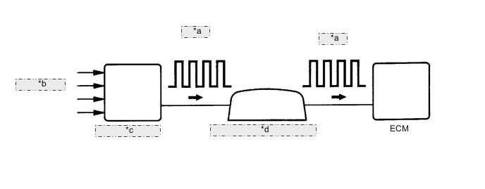
| *a | 4-Pulse |
| *b | from Speed Sensor |
| *c | Skid Control ECU |
| *d | Combination Meter Assembly |
| DTC No. | Detection Item | DTC Detection Condition | Trouble Area | MIL | Memory | Note |
|---|---|---|---|---|---|---|
| P050031 | Vehicle Speed Sensor "A" No Signal | When the engine coolant temperature sensor is normal and the counter gear speed is 300 rpm or more, the vehicle speed signal is not input for 2 sec. or more (1-trip detection logic). |
|
Comes on | DTC stored | SAE: P0500 |
MONITOR DESCRIPTION
The ECM assumes that the vehicle is being driven when the transmission counter gear indicates more than 300 rpm and over 30 seconds have passed since the park/neutral position switch assembly was turned off. If there is no vehicle speed signal with these conditions satisfied, the ECM concludes that there is a vehicle speed signal malfunction. The ECM will illuminate the MIL and store this DTC.
WIRING DIAGRAM
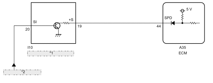
| *1 | Combination Meter Assembly |
| *2 | from Skid Control ECU |
CAUTION / NOTICE / HINT
Note
Perform registration and/or initialization when parts related to the automatic transaxle are replaced.
PROCEDURE
-
READ VALUE USING GTS (VEHICLE SPEED)
-
Drive the vehicle and check whether the operation of the speedometer in the combination meter assembly is normal.
Tech Tips
-
The vehicle speed sensor is operating normally if the speedometer reading is normal.
-
If the speedometer does not operate, check it by following the procedure described for a speedometer malfunction.
-
-
Connect the GTS to the DLC3.
-
Turn the engine switch on (IG).
-
Turn the GTS on.
-
Enter the following menus: Powertrain / Transmission / Data List / Vehicle Speed.
Powertrain > Transmission > Data ListTester Display Vehicle Speed -
Drive the vehicle.
-
Read the value displayed on the GTS.
OK Vehicle speeds displayed on the GTS and speedometer display are equal. Result Proceed to OK NG
OK 
CHECK FOR INTERMITTENT PROBLEMS Click here
NG 
-
-
CHECK COMBINATION METER SYSTEM
-
Inspect the circuits that send vehicle speed signals to this system in the meter system.
-
During inspection for the meter section, if there is an instruction that indicates to go back to inspections for each system, proceed to the next step.
Result Proceed to NEXT
NEXT
-
-
CHECK HARNESS AND CONNECTOR (COMBINATION METER ASSEMBLY - ECM)
-
Disconnect the I10 combination meter assembly connector.
-
Disconnect the A35 ECM connector.
-
Measure the resistance according to the value(s) in the table below.
Standard Resistance Tester Connection Condition Specified Condition I10-19 (+S) - A35-44 (SPD) Always Below 1 Ω Result Proceed to OK NG
OK
REPLACE ECM Click here
NG
REPAIR OR REPLACE HARNESS OR CONNECTOR
-