POWER WINDOW CONTROL SYSTEM Front Passenger Side Power Window Manual Function does not Operate with Front Passenger Side Power Window Switch
DESCRIPTION
If the front passenger side manual up/down function does not operate, a malfunction may be present in the front power window regulator motor assembly (for front passenger side)*1 or front door window regulator sub-assembly (for front passenger side)*2, front power window regulator switch assembly (for front passenger side), power window regulator master switch assembly or wire harness.
-
*1: w/o Regulator
-
*2: w/ Regulator
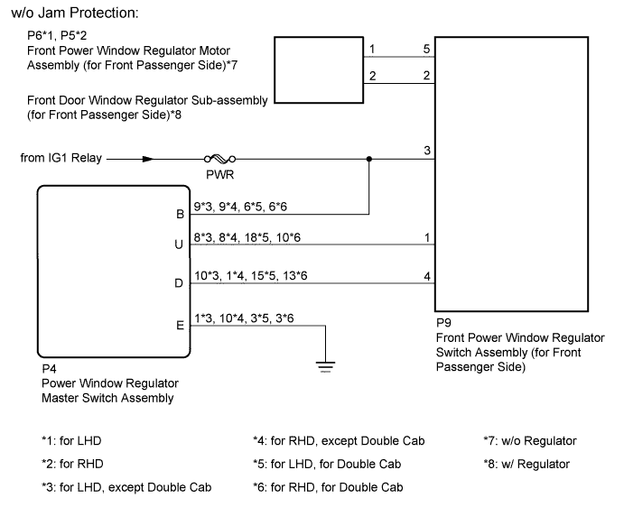
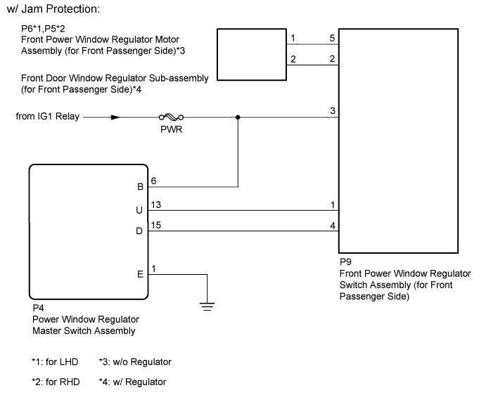
WIRING DIAGRAM
INSPECTION PROCEDURE
Note
Inspect the fuses for circuits related to this system before performing the following inspection procedure.
PROCEDURE
-
CHECK HARNESS AND CONNECTOR (FRONT POWER WINDOW REGULATOR SWITCH ASSEMBLY [FOR FRONT PASSENGER SIDE] - BATTERY)
-
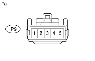
Text in Illustration *a Front view of wire harness connector
(to Front Power Window Regulator Switch Assembly [for Front Passenger Side])
Disconnect the P9 front power window regulator switch assembly (for front passenger side) connector.
-
Measure the voltage according to the value(s) in the table below.
Standard Voltage Tester Connection Switch Condition Specified Condition P9-3 - Body ground Ignition switch ON 11 to 14 V P9-3 - Body ground Ignition switch off Below 1 V
NG 
REPAIR OR REPLACE HARNESS OR CONNECTOR
OK 
-
-
INSPECT FRONT POWER WINDOW REGULATOR SWITCH ASSEMBLY (FOR FRONT PASSENGER SIDE)
-
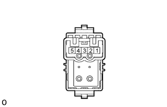
Remove the front power window regulator switch assembly (for front passenger side).
-
Measure the resistance according to the value(s) in the table below.
Standard Resistance Tester Connection Switch Condition Specified Condition 5 - 4
2 - 3
UP Below 1 Ω 5 - 4
2 - 1
OFF Below 1 Ω 5 - 3
2 - 1
DOWN Below 1 Ω
NG
REPLACE FRONT POWER WINDOW REGULATOR SWITCH ASSEMBLY (FOR FRONT PASSENGER SIDE)
OK
-
-
CHECK HARNESS AND CONNECTOR (FRONT POWER WINDOW REGULATOR SWITCH [FOR FRONT PASSENGER SIDE] - FRONT POWER WINDOW REGULATOR MOTOR [FOR FRONT PASSENGER SIDE]) OR FRONT DOOR WINDOW REGULATOR [FOR FRONT PASSENGER SIDE])
-
*1: for LHD
-
*2: for RHD
-
Disconnect the P4 front power window regulator switch assembly (for front passenger side) connector.
-
w/o Regulator:
-
Disconnect the P5*1 or P6*2 front power window regulator motor assembly (for front passenger side) connector.
-
-
w/ Regulator:
-
Disconnect the P5*1 or P6*2 front door window regulator sub-assembly (for front passenger side) connector.
-
-
Measure the resistance according to the value(s) in the table below.
Standard Resistance for LHD Tester Connection Condition Specified Condition P9-5 - P6-1 Always Below 1 Ω P9-2 - P6-2 Always Below 1 Ω P9-5 or P6-1 - Body ground Always 10 kΩ or higher P9-2 or P6-2 - Body ground Always 10 kΩ or higher for RHD Tester Connection Condition Specified Condition P9-5 - P5-1 Always Below 1 Ω P9-2 - P5-2 Always Below 1 Ω P9-5 or P5-1 - Body ground Always 10 kΩ or higher P9-2 or P5-2 - Body ground Always 10 kΩ or higher
NG
REPAIR OR REPLACE HARNESS OR CONNECTOR
OK
-
-
INSPECT FRONT POWER WINDOW REGULATOR MOTOR ASSEMBLY (FOR FRONT PASSENGER SIDE) OR FRONT DOOR WINDOW REGULATOR SUB-ASSEMBLY (FOR FRONT PASSENGER SIDE)
-
w/o Regulator:
-
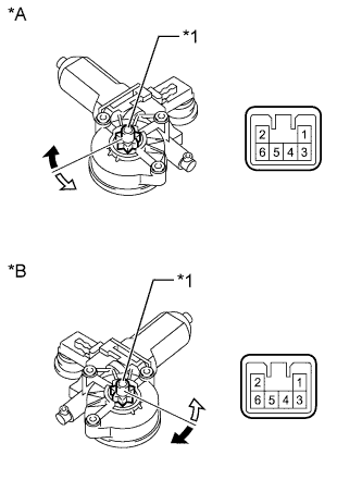
Text in Illustration *A for LHD *B for RHD *1 Motor Gear 
Clockwise 
Counterclockwise Remove the front power window regulator motor assembly (for front passenger side).
-
Apply battery voltage to connector terminals 1 and 2.
-
Check that the motor gear rotates smoothly as follows.
OK for LHD Measurement Condition Specified Condition Battery positive (+) → 2
Battery negative (-) → 1
Motor gear rotates clockwise Battery positive (+) → 1
Battery negative (-) → 2
Motor gear rotates counterclockwise for RHD Measurement Condition Specified Condition Battery positive (+) → 2
Battery negative (-) → 1
Motor gear rotates counterclockwise Battery positive (+) → 1
Battery negative (-) → 2
Motor gear rotates clockwise
-
-
w/ Regulator:
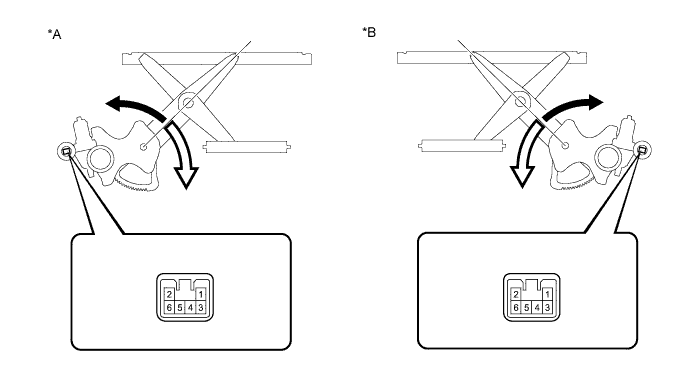
Text in Illustration *A for LHD *B for RHD Up Down
-
Remove the front door window regulator sub-assembly (for front passenger side).
-
Apply battery voltage to connector terminals 1 and 2.
-
Check that the arm of window regulator rotates smoothly as follows.
OK for LHD Measurement Condition Specified Condition Battery positive (+) → 2
Battery negative (-) → 1
Arm of window regulator rotates clockwise (Up) Battery positive (+) → 1
Battery negative (-) → 2
Arm of window regulator rotates counterclockwise (Down) for RHD Measurement Condition Specified Condition Battery positive (+) → 2
Battery negative (-) → 1
Arm of window regulator rotates counterclockwise (Up) Battery positive (+) → 1
Battery negative (-) → 2
Arm of window regulator rotates clockwise (Down)
Result Result Proceed to OK A NG (w/o Regulator) B NG (w/ Regulator) C -
B
REPLACE FRONT POWER WINDOW REGULATOR MOTOR ASSEMBLY (FOR FRONT PASSENGER SIDE)
C
REPLACE FRONT DOOR REGULATOR SUB-ASSEMBLY (FOR FRONT PASSENGER SIDE)
A
-
-
CHECK HARNESS AND CONNECTOR (POWER WINDOW REGULATOR MASTER SWITCH ASSEMBLY - FRONT POWER WINDOW REGULATOR SWITCH ASSEMBLY [FOR FRONT PASSENGER SIDE])
-
except Double Cab, w/o Jam Protection:
-
Disconnect the P4 power window regulator master switch assembly connector.
-
Disconnect the P9 front power window regulator switch assembly (for front passenger side) connector.
-
Measure the resistance according to the value(s) in the table below.
Standard Resistance for LHD Tester Connection Condition Specified Condition P4-8 (U) - P9-1 Always Below 1 Ω P4-10 (D) - P9-4 Always Below 1 Ω P4-8 (U) or P9-1 - Body ground Always 10 kΩ or higher P4-10 (D) or P9-4 - Body ground Always 10 kΩ or higher for RHD Tester Connection Condition Specified Condition P4-8 (U) - P9-1 Always Below 1 Ω P4-1 (D) - P9-4 Always Below 1 Ω P4-8 (U) or P9-1 - Body ground Always 10 kΩ or higher P4-1 (D) or P9-4 - Body ground Always 10 kΩ or higher
-
-
for Double Cab, w/o Jam Protection:
-
Disconnect the P4 power window regulator master switch assembly connector.
-
Disconnect the P9 front power window regulator switch assembly (for front passenger side) connector.
-
Measure the resistance according to the value(s) in the table below.
Standard Resistance for LHD Tester Connection Condition Specified Condition P4-18 (U) - P9-1 Always Below 1 Ω P4-15 (D) - P9-4 Always Below 1 Ω P4-18 (U) or P9-1 - Body ground Always 10 kΩ or higher P4-15 (D) or P9-4 - Body ground Always 10 kΩ or higher for RHD Tester Connection Condition Specified Condition P4-10 (U) - P9-1 Always Below 1 Ω P4-13 (D) - P9-4 Always Below 1 Ω P4-10 (U) or P9-1 - Body ground Always 10 kΩ or higher P4-13 (D) or P9-4 - Body ground Always 10 kΩ or higher
-
-
w/ Jam Protection:
-
Disconnect the P4 power window regulator master switch assembly connector.
-
Disconnect the P9 front power window regulator switch assembly (for front passenger side) connector.
-
Measure the resistance according to the value(s) in the table below.
Standard Resistance Tester Connection Condition Specified Condition P4-13 (U) - P9-1 Always Below 1 Ω P4-15 (D) - P9-4 Always Below 1 Ω P4-13 (U) or P9-1 - Body ground Always 10 kΩ or higher P4-15 (D) or P9-4 - Body ground Always 10 kΩ or higher
-
NG
REPAIR OR REPLACE HARNESS OR CONNECTOR
OK 
REPLACE POWER WINDOW REGULATOR MASTER SWITCH ASSEMBLY
-