PANORAMIC VIEW MONITOR SYSTEM
-
FUNCTION OF MAIN COMPONENTS
-
The components have the following functions:
Component Function Front Television Camera Assembly Outputs a video signal of the area in front of the vehicle to the parking assist ECU. Rear Television Camera Assembly Outputs a video signal of the area to the rear of the vehicle to the parking assist ECU. Side Television Camera Assembly LH Outputs a video signal of the area to the left side of the vehicle to the parking assist ECU. Side Television Camera Assembly RH Outputs a video signal of the area to the right side of the vehicle to the parking assist ECU. Parking Assist ECU
-
Combines video signals from the front, rear, left and right television camera assemblies to create a seamless overhead image.
-
Calculates each guideline based on information signals from each ECU and sensor, combines the lines with the panoramic view display and images from each television camera assembly, and outputs a video signal to the radio and display receiver assembly.
-
Turns each television camera assembly on and off according to the input shift position signal and panoramic view monitor main switch signal.
-
Combines detection information with the currently displayed panoramic view monitor screen according to signals from the clearance warning ECU assembly and outputs a video signal to the radio and display receiver assembly.
Panoramic View Monitor Main Switch Switches the panoramic view monitor screen display. Steering Sensor Detects the angle of the steering wheel and sends the resulting signals to the parking assist ECU. Radio and Display Receiver Assembly
-
Displays the video signal from the parking assist ECU on the screen.
-
Outputs the screen status to the parking assist ECU, such as when the screen display mode switches and the automatic display mode turns on and off.
Skid Control ECU Transmits received vehicle speed signals to the parking assist ECU. Main Body ECU (Multiplex Network Body ECU) Outputs the front door and back door opening and closing signals, etc., to the parking assist ECU. Clearance Warning ECU Assembly Outputs obstacle detection information to the parking assist ECU. Park/Neutral Position Switch Assembly*1 Transmits the shift position signal to the ECM and TCM*2. Back-up Light Switch Assembly*3 Transmits the on/off signals of the back-up light switch assembly to the parking assist ECU. ECM and TCM*2 Transmits the shift position signal to the parking assist ECU.
-
*1: Models with automatic transaxle or CVT
-
*2: Models with U660F automatic transaxle
-
*3: Models with manual transaxle
-
-
-
SYSTEM CONTROL
-
Each screen of the panoramic view monitor system displays guide lines, estimated course lines, etc., together according to the selected screen display mode to inform the driver of the tire positions and trajectories which cannot be directly seen from the driver seat.
-
When the Toyota parking assist-sensor system detects an obstacle, obstacle detection information is displayed superimposed on the screen according to each screen display mode.
-
-
OPERATING CONDITION
-
Manual display mode and automatic display mode are provided for the display method of the panoramic view monitor system.
-
Manual Display Mode
-
Manual display mode is a method of displaying the panoramic view monitor screen according to the needs of the driver via operation of the panoramic view monitor main switch.
-
The screen displayed when the panoramic view monitor main switch is pressed differs according to the shift position.
-
When the vehicle speed exceeds 12 km/h (7.5 mph), the panoramic view monitor screen ends and switches to display the navigation screen or information screen.
-
-
Automatic Display Mode
-
When starting off and stopping the vehicle in automatic display mode, it is possible to display the "panoramic view and wide front view" or "side simultaneous view screen" automatically instead of by pressing the panoramic view monitor main switch. Refer to the following chart for the screen display conditions.
-
The automatic display mode can be set with the AUTO mode switch displayed on the screen.
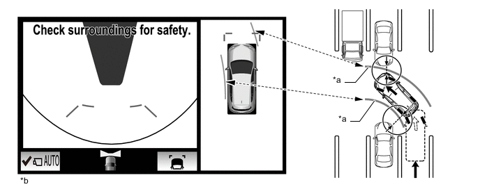
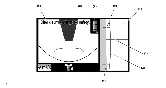
Automatic Display Mode Screen Display Conditions Display Screen Display Conditions Assumed Situation Display when starting off Vehicle speed is 10 km/h (6 mph) or less and shift lever is not in P* or R 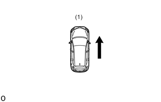
(1) Check surroundings Display when stopping vehicle Shift lever is not in P* or R and vehicle speed becomes 10 km/h (6 mph) or less 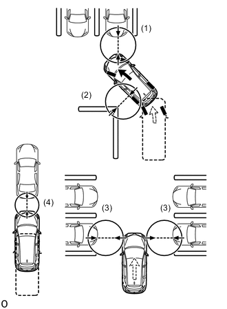
(1) Forward blind spot
(2) Inside blind spot
(3) Vehicle width
(4) Vehicle-to-vehicle distance
*: Models with automatic transaxle or CVT
-
-
-
-
FUNCTION
-
Panoramic View Monitor System Display Range
-
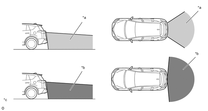
Panoramic View
-
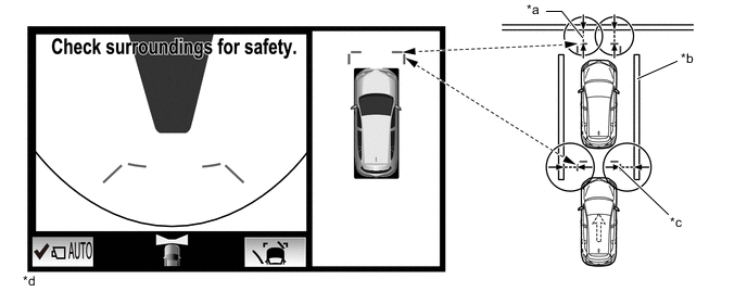
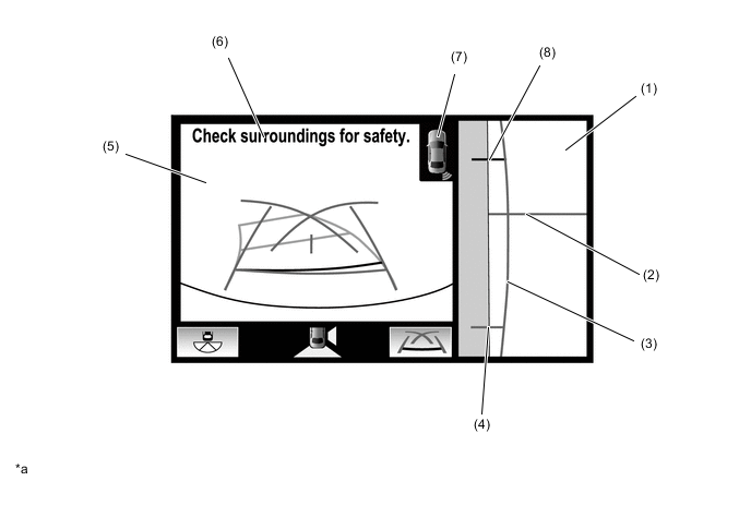
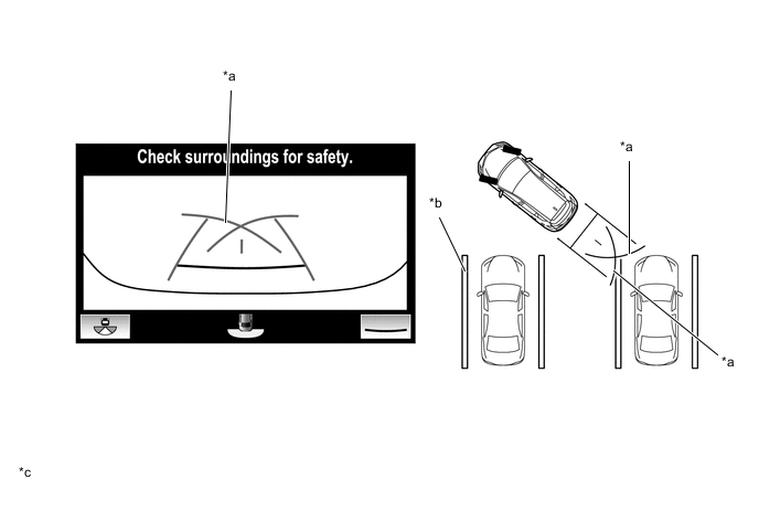
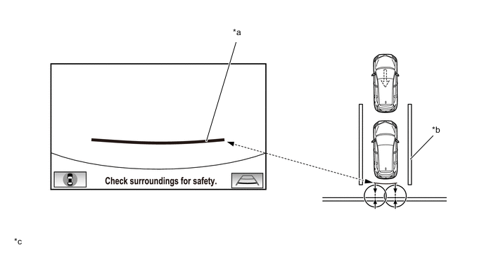
The display range of the panoramic view image is as follows. However, the range differs according to the vehicle and road surface conditions.
Note
The panoramic view image display range is limited and objects in the blind spot close to the vehicle or objects taller than the road surface may not be displayed. Also, the clearness at the four corners may be reduced. Take care when driving.
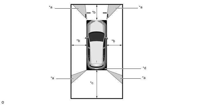
*a Image Combination Processing Area *b Approx. 2.0 m (6.6 ft.) *c Approx. 3.0 m (9.8 ft.) *d Blind Spot
-
-
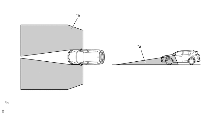
Wide Front View
-
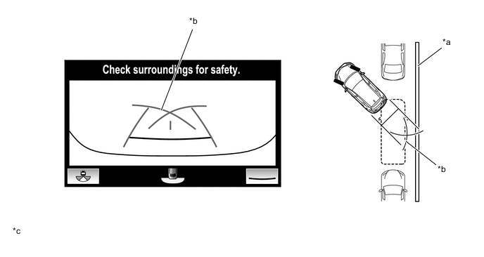
The wide front view image is an image of the following front television camera assembly imaging range. However, the range differs according to the vehicle and road surface conditions.
Tech Tips
Since the driver's sense of the distance in front of the vehicle differs from actual conditions, masking (mask area) is used.
Note
The image display range is limited. Also, since objects near either end of the bumper and objects positioned directly under and near the bumper may not be displayed, take care when driving.
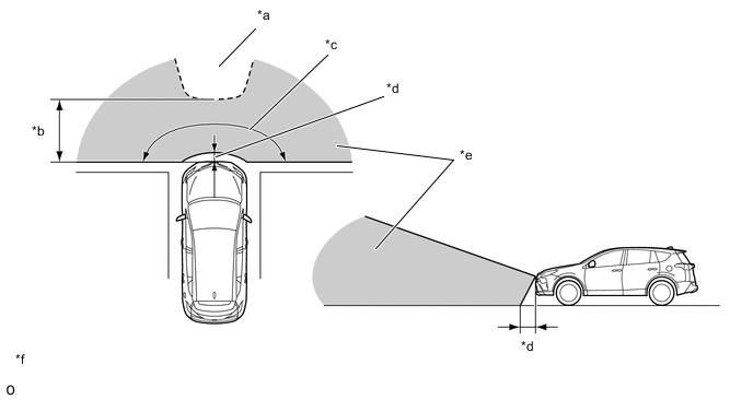
*a Mask Range *b Approx. 5.0 m (16.4 ft.) *c Approx. 180° *d Approx. 0.4 m (1.3 ft.) *e Front Television Camera Assembly Imaging Range *f The illustrations shown are examples only.
-
-
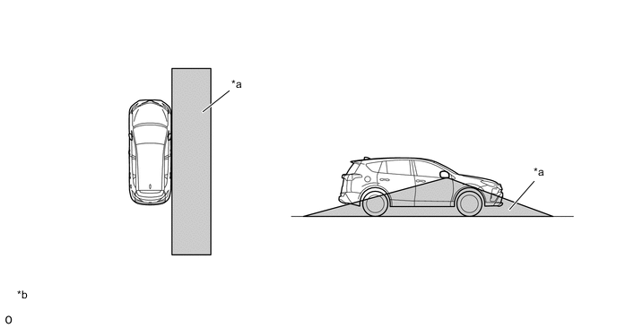
Rear View
-
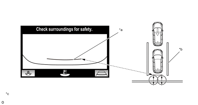
The rear view image is an image of the following rear television camera assembly imaging range. However, the range differs according to the vehicle and road surface conditions.
Note
The image display range is limited. Also, since objects near either end of the bumper and objects positioned directly under and near the bumper may not be displayed, take care when driving.
*a Rear Television Camera Assembly Imaging Range (Rear View) *b Rear Television Camera Assembly Imaging Range (Wide Rear View) *c The illustrations shown are examples only. - -
-
-
Side Simultaneous View
-
The side simultaneous view image is an image of the following side television camera assembly imaging range. However, the range differs according to the vehicle and road surface conditions.
Note
The image display range is limited. Also, since objects near either end of the bumper and objects positioned directly under and near the bumper may not be displayed, take care when driving.
*a Side Television Camera Assembly Imaging Range *b The illustrations shown are examples only.
-
-
Side View
-
The side view image is an image of the following side television camera assembly imaging range. However, the range differs according to the vehicle and road surface conditions.
Note
The image display range is limited. Also, since objects near either end of the bumper and objects positioned directly under and near the bumper may not be displayed, take care when driving.
*a Side Television Camera Assembly Imaging Range *b The illustrations shown are examples only.
-
-
-
Panoramic View Monitor System Screen and Operation
-
Each screen of the panoramic view monitor system displays guide lines, estimated course lines, etc., together according to the selected screen display mode to inform the driver of the tire positions and trajectories which cannot be directly seen from the driver seat.
-
When the Toyota parking assist-sensor system detects an obstacle, obstacle detection information is displayed superimposed on the screen according to each screen display mode.
-
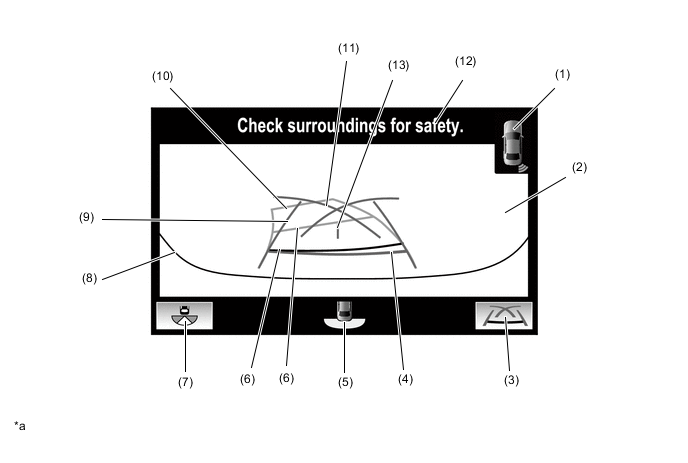
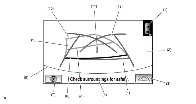
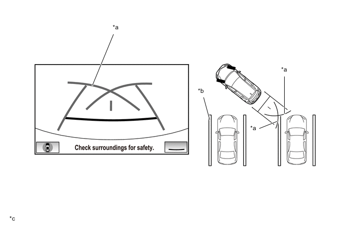
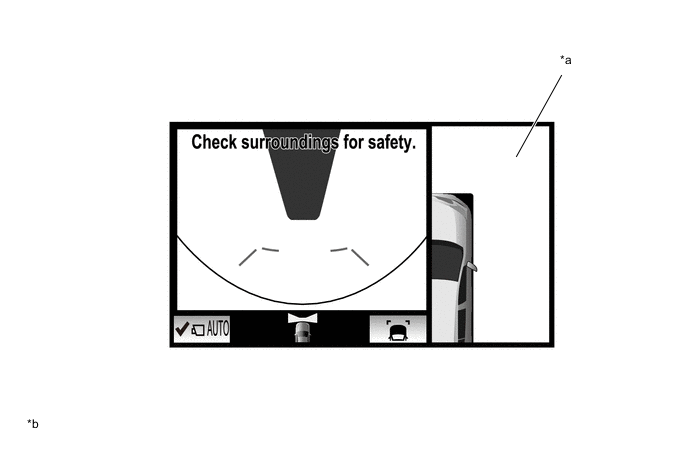
Panoramic View and Wide Front View
-
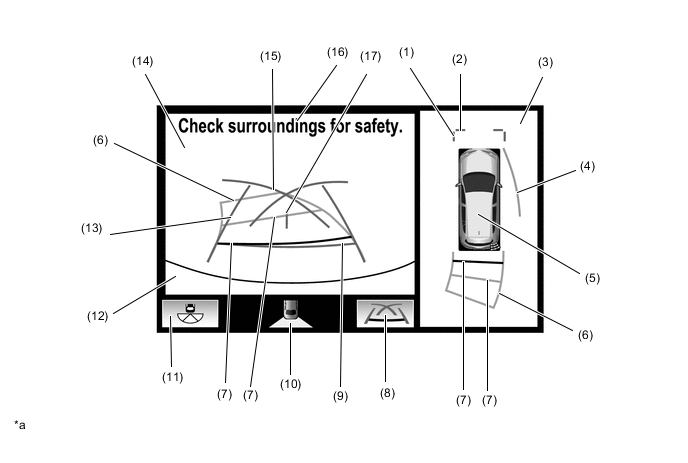
The panoramic view created by combining images from each television camera assembly and the image from the front television camera assembly are displayed simultaneously. The images assist with confirming the safety of the surroundings and areas to the left and right of the vehicle at locations with poor visibility, such as intersections and T-junctions.
Tech Tips
When the outer rear view mirror assemblies are retracted, the side and wide front view is displayed.
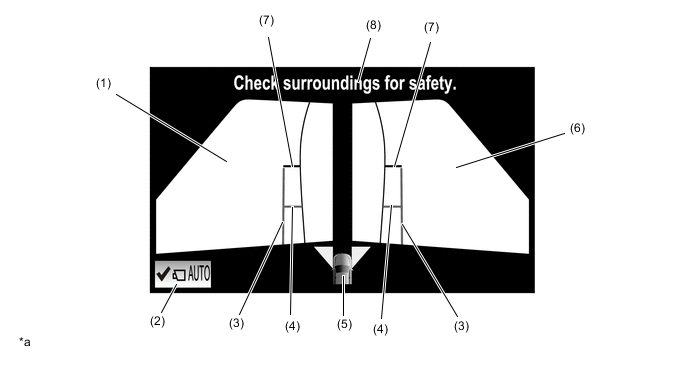
Figure 1. Panoramic View and Wide Front View Screen Display Contents
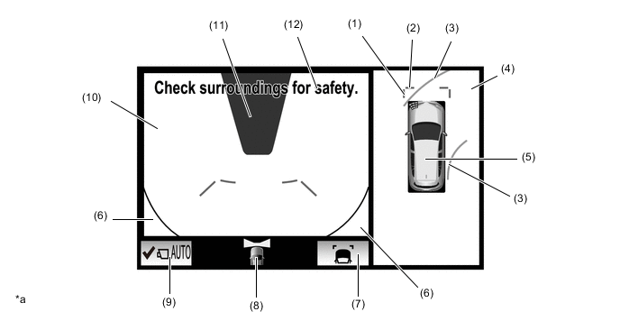
*a The illustration shown is an example only. The illustration may differ from the actual vehicle screen. - - Item Description (1) Front Vehicle Width Extension Line (Blue) These lines are vehicle width extension lines. The lines displayed are wider than the actual vehicle width. (2) Front Distance Guide Line (Blue) These lines are distance guide lines showing the distance forward from the edge of the front bumper. (Approx. 1.0 m (3.3 ft.)) (3) Forward Estimated Course Line* (Yellow)
-
Displays the estimated course calculated from the steering angle.
-
Displays the estimated course ahead of the front of the vehicle on the outside of the steering direction, and the estimated course ahead of the rear of the vehicle on the inside of the steering direction.
(4) Panoramic View Display Displays an overhead image created by combining images from the vehicle front, rear, left and right side television camera assemblies. (5) Panoramic View Display Icon
-
Displays the vehicle position in the panoramic view display.
-
When the Toyota parking assist-sensor system detects an obstacle, the obstacle detection direction and distance are displayed superimposed on the screen.
(6) Vehicle Reflection Parts of the vehicle (grille and bumper) are displayed. (7) Display Mode Switch Button Pressing this button changes the display mode. (8) Camera Direction Display Vehicle Icon Indicates that the "wide front view screen" is displayed on the left side of the screen. (9) AUTO Mode Button Can be used to turn the automatic display mode on and off. (10) Wide Front View Display An image captured by the front television camera assembly of the area in front of the vehicle. (11) Masking Since the driver's sense of the distance in front of the vehicle differs from actual conditions, masking is used. (12) Warning Message Warns the driver according to the message on the display. Tech Tips
*: Displayed when the guide line display is set to "Estimated Course Line Display Mode" and the steering angle is not positioned straight ahead.
-
-
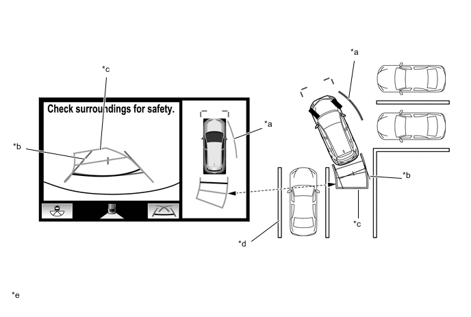
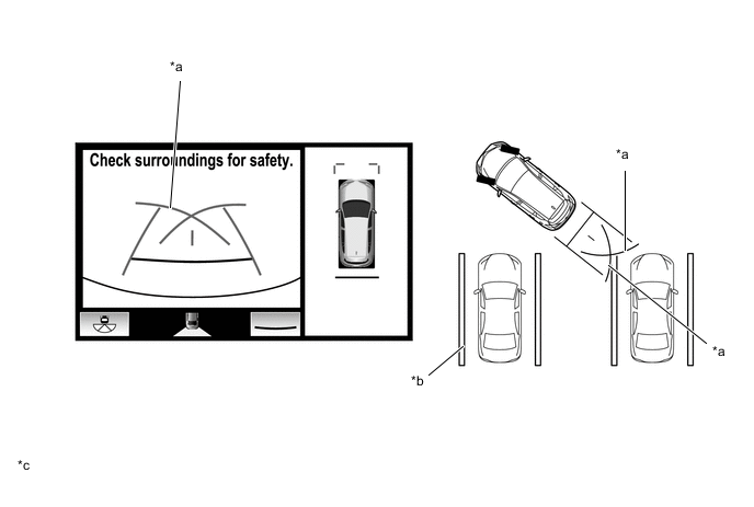
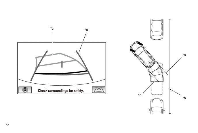
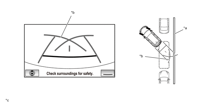
Estimated Course Line Display Mode
-
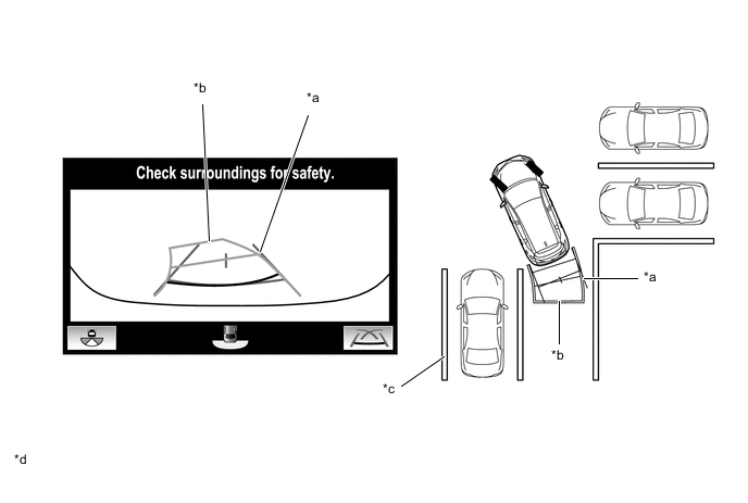
The forward estimated course lines assist with driving operations performed to avoid obstacles by guiding the steering angle according to the estimated course on the outside and inside of the steering direction to prevent overlapping of each guide line with obstacles, etc.
*a Forward Estimated Course Line *b The illustrations shown are examples only. The illustrations may differ from the actual vehicle screens. -
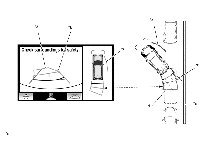
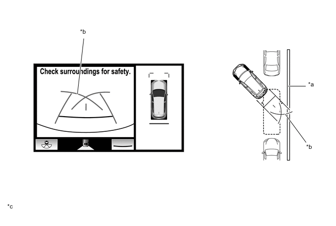
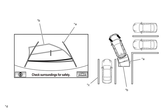
Distance Guide Line Display Mode
-
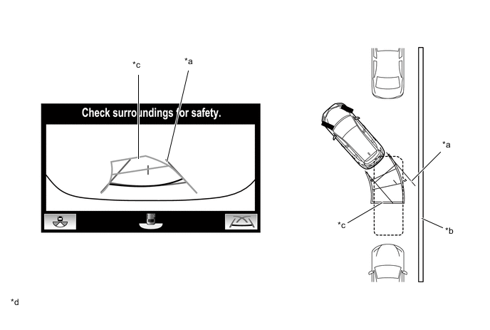
Forward perpendicular parking operations are assisted by driving forward while steering so that the front distance guide lines and vehicle width extension lines do not overlap the curb and actual white lines, etc.
*a Front Distance Guide Line *b Parking Space Line *c Vehicle Width Extension Line *d The illustrations shown are examples only. The illustrations may differ from the actual vehicle screens. -
Side and Wide Front View Screen Display Mode (When Outer Rear View Mirror Assemblies are Retracted)
-
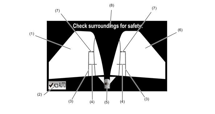
When the outer rear view mirror assemblies are retracted, the panoramic view does not display. Instead, an enlarged image from the side television camera RH and the wide front view screen are displayed to assist with confirming the safety of the surroundings and parking close to another object, etc.
Figure 2. Side and Wide Front View Screen Display Contents
*a The illustration shown is example only. The illustration may differ from the actual vehicle screen. - - Item Description (1) Side View (Right Side) Display An image of the area to the left of the vehicle captured by the side television camera assembly RH. (2) Front Tire Contact Line (Blue) A guide line showing the front right tire contact position. (3) Vehicle Width Parallel Line (Blue) A vehicle width guide line including the outer rear view mirror assembly. (4) Rear Tire Contact Line (Blue) A guide line showing the rear right tire contact position. (5) Warning Message Warns the driver according to the message on the display. (6) Wide Front View Display An image captured by the front television camera assembly of the area in front of the vehicle. (7) Toyota Parking Assist-sensor System Icon Displayed when the Toyota parking assist-sensor system detects an obstacle. The obstacle detection direction and distance are displayed superimposed on the screen. (8) Front Distance Guide Line (Red) This line is distance guide line showing the distance forward from the edge of the front bumper. (Approximately 0.5 m (1.6 ft.))
-
-
Panoramic View and Rear View
-
The panoramic view display created by combining images from the front, rear, left and right side television camera assemblies and the image from the rear television camera assembly are displayed simultaneously. The images assist with confirming the safety of the surroundings and operating the vehicle in reverse.
Figure 3. Panoramic View and Rear View Screen Display Contents
*a The illustration shown is example only. The illustration may differ from the actual vehicle screen. - - Item Description (1) Front Vehicle Width Extension Line (Blue) These lines are vehicle width extension lines. The lines displayed are wider than the actual vehicle width. (2) Front Distance Guide Line (Blue) These lines are distance guide lines showing the distance forward from the edge of the front bumper. (Approx. 1.0 m (3.3 ft.)) (3) Panoramic View Display Displays an overhead image created by combining images from the vehicle front, rear, left and right side television camera assemblies. (4) Side Estimated Course Line*1 (Yellow)
-
Displays the estimated course calculated from the steering angle.
-
Displays the estimated course on the outside of the steering direction.
(5) Panoramic View Display Icon*2
-
Displays the vehicle position in the panoramic view display.
-
When the Toyota parking assist-sensor system detects an obstacle, the obstacle detection direction and distance are displayed superimposed on the screen.
(6) Rear Estimated Course Line*3 (Yellow) Moves in sync with the steering wheel to indicate the estimated reverse course of the vehicle. (7) Rear Distance Guide Line (Yellow/Red)*1 These lines are distance guide lines showing the distance from the edge of the rear bumper. (Approx. 1.0 m (3.3 ft.): yellow, approx. 0.5 m (1.6 ft.): red) (8) Display Mode Switch Button Pressing this button changes the display mode. (9) Rear Distance Guide Line (Blue*4) These lines are distance guide lines showing the distance from the edge of the rear bumper. (Approx. 0.5 m (1.6 ft.)) (10) Camera Direction Display Vehicle Icon Indicates that the rear view screen is displayed on the right side of the screen. (11) Camera Angle Mode Switch Button Switches the wide rear view screen. (12) Edge of Rear Bumper The edge of the rear bumper is displayed on the screen. (13) Rear Vehicle Width Extension Line*5 (Blue) Indicates the estimated vehicle width. (14) Rear View Display An image captured by the rear television camera assembly of the area to the rear of the vehicle. (15) Parking Assist Guide Line*6 (Blue) Indicates the path the vehicle will follow when the driver turns the steering wheel fully. (16) Warning Message Warns the driver according to the message on the display. (17) Vehicle Center Guide Line (Blue) Indicates the estimated position on the ground of the center of the vehicle. Tech Tips
*1: Displayed when the guideline display is set to "Estimated Course Line Display Mode" and the steering angle is not positioned straight ahead.
*2: The color of the panoramic view vehicle icon can be changed. Refer to the Repair Manual for the details.
*3: Displayed when the guideline display is set to "Estimated Course Line Display Mode".
*4: Turns red in "Parking Assist Guide Line Display Mode" and "Distance Guide Line Display Mode".
*5: Not displayed when the steering angle is approximately straight ahead.
*6: The side estimated course line or rear estimated course line and the parking assist guide line cannot be displayed simultaneously.
-
-
Estimated Course Line Display Mode (Perpendicular Parking (Entering Parking Space))
-
The estimated course lines inform the driver of the steering angle when driving in reverse. By driving the vehicle in reverse while steering to match the rear estimated course lines with the parking space boundary line, the vehicle can be guided into the parking space. Also, the side estimated course line assists with operations performed to avoid contact with obstacles, etc., on the outside of the steering direction.
-
The rear vehicle width extension lines can be used to determine whether the vehicle is parked straight in the parking space by confirming whether the parking space lines and rear vehicle width extension lines are crossed or parallel.
*a Side Estimated Course Line *b Rear Vehicle Width Extension Line *c Rear Estimated Course Line *d Parking Space Line *e The illustrations shown are examples only. The illustrations may differ from the actual vehicle screens. - - -
Estimated Course Line Display Mode (Parallel Parking)
-
The estimated course lines inform the driver of the steering angle when driving in reverse, such as when parallel parking. By driving the vehicle in reverse while steering to match the rear estimated course lines with the side of the road or parking space boundary line, etc. of the desired parking position, the vehicle can be guided into the parking space. Also, the side estimated course line assists with operations performed to avoid contact with obstacles, etc., on the outside of the steering direction.
-
The rear vehicle width extension lines can be used to determine whether the vehicle is parked straight in the desired parking position by confirming the status of the shoulder and parking space lines, etc., and rear vehicle width extension lines.
*a Side Estimated Course Line *b Rear Vehicle Width Extension Line *c Shoulder and Parking Space Lines, etc. *d Rear Estimated Course Line *e The illustrations shown are examples only. The illustrations may differ from the actual vehicle screens. - - -
Parking Assist Guide Line Display Mode (Perpendicular Parking (Entering Parking Space))
-
The parking assist guide lines inform the driver of the steering angle when the steering wheel is fully turned while driving in reverse. By driving the vehicle in reverse to match the parking assist guide lines with the parking space boundary line, the vehicle can be guided to an appropriate position to start turning the steering wheel.
*a Parking Assist Guide Line *b Shoulder and Parking Space Lines, etc. *c The illustrations shown are examples only. The illustrations may differ from the actual vehicle screens. - - -
Parking Assist Guide Line Display Mode (Parallel Parking)
-
The parking assist guidelines are used as a guide to know where to stop the vehicle when driving the vehicle straight back in reverse, such as when parallel parking. By driving the vehicle in reverse until the parking assist guidelines match the side of the road or parking space boundary line, the vehicle can be guided to an appropriate position to start turning the steering wheel.
*a Parking Space Line *b Parking Assist Guide Line *c The illustrations shown are examples only. The illustrations may differ from the actual vehicle screens. - - -
Side and Rear View Screen Display Mode (when Outer Rear View Mirror Assemblies are Retracted)
-
When the outer rear view mirror assemblies are retracted, the side television camera assembly RH and rear television camera assembly images simultaneously display and assist with confirming the safety of the surroundings and parking close to the curb, etc., with the vehicle width parallel lines.
Figure 4. Side and Rear View Screen Display Contents
*a The illustration shown is example only. The illustration may differ from the actual vehicle screen. - - Item Description (1) Side View (Right Side) Display An image of the area to the right of the vehicle captured by the side television camera assembly RH. (2) Front Tire Contact Line (Blue) A guide line showing the front right tire contact position. (3) Vehicle Width Parallel Line (Blue) A vehicle width guide line including the outer rear view mirror assembly. (4) Rear Tire Contact Line (Blue) A guide line showing the rear right tire contact position. (5) Rear View Display An image captured by the rear television camera assembly of the area to the rear of the vehicle. (6) Warning Message Warns the driver according to the message on the display. (7) Toyota Parking Assist-sensor System Icon Displayed when the Toyota parking assist-sensor system detects an obstacle. The obstacle detection direction and distance are displayed superimposed on the screen. (8) Front Distance Guide Line (Red) This line is distance guide line showing the distance forward from the edge of the front bumper. (Approximately 0.5 m (1.6 ft.))
-
-
Wide Rear View
-
An enlarged image from the rear television camera assembly is displayed to assist with confirming the safety of the left and right sides of the vehicle while driving in reverse.
Figure 5. Wide Rear View Screen Display Contents
*a The illustration shown is example only. The illustration may differ from the actual vehicle screen. - - Item Description (1) Toyota Parking Assist-sensor System Icon Displayed when the Toyota parking assist-sensor system detects an obstacle. The obstacle detection direction and distance are displayed superimposed on the screen. (2) Wide Rear View Display An image captured by the rear television camera assembly of the area to the rear of the vehicle. (3) Display Mode Switch Button Pressing this button changes the display mode. (4) Rear Distance Guide Line (Blue*1) These lines are distance guide lines showing the distance from the edge of the rear bumper. (Approx. 0.5 m (1.6 ft.)) (5) Camera Direction Display Vehicle Icon Indicates that the wide rear view screen is displayed. (6) Rear Distance Guide Line (Yellow/Red)*2 These lines are distance guide lines showing the distance from the edge of the rear bumper. (Approx. 1.0 m (3.3 ft.): yellow, approx. 0.5 m (1.6 ft.): red) (7) Camera Angle Mode Switch Button Switches the rear view screen. (8) Edge of Rear Bumper The edge of the rear bumper is displayed on the screen. (9) Rear Vehicle Width Extension Line*3 (Blue) Indicates the estimated vehicle width. (10) Rear Estimated Course Line*4 (Yellow) Moves in sync with the steering wheel to indicate the estimated reverse course of the vehicle. (11) Parking Assist Guide Line*5 (Blue) Indicates the path the vehicle will follow when the driver turns the steering wheel fully. (12) Warning Message Warns the driver according to the message on the display. (13) Vehicle Center Guide Line (Blue) Indicates the estimated position on the ground of the center of the vehicle. Tech Tips
*1: Turns red in "Parking Assist Guide Line Display Mode" and "Distance Guide Line Display Mode".
*2: Displayed when the guideline display is set to "Estimated Course Line Display Mode" and the steering angle is not positioned straight ahead.
*3: Not displayed when the steering angle is approximately straight ahead.
*4: Displayed when the guideline display is set to "Estimated Course Line Display Mode".
*5: The rear estimated course line and the parking assist guide line cannot be displayed simultaneously.
-
Estimated Course Line Display Mode (Perpendicular Parking (Entering Parking Space))
-
The estimated course lines inform the driver of the steering angle when driving in reverse. By driving the vehicle in reverse while steering to match the rear estimated course lines with the parking space boundary line, the vehicle can be guided into the parking space.
-
The rear vehicle width extension lines can be used to determine whether the vehicle is parked straight in the parking space by confirming the status of the parking space lines and rear vehicle width extension lines.
*a Rear Vehicle Width Extension Line *b Rear Estimated Course Line *c Parking Space Line *d The illustrations shown are examples only. The illustrations may differ from the actual vehicle screens. -
Estimated Course Line Display Mode (Parallel Parking)
-
The estimated course lines inform the driver of the steering angle when driving in reverse, such as when parallel parking. By driving the vehicle in reverse while steering to match the rear estimated course lines with the side of the road or parking space boundary line, etc. of the desired parking position, the vehicle can be guided into the parking space.
-
The rear vehicle width extension lines can be used to determine whether the vehicle is parked straight in the desired parking position by confirming the status of the shoulder and parking space lines, etc., and rear vehicle width extension lines.
*a Rear Vehicle Width Extension Line *b Shoulder and Parking Space Lines, etc. *c Rear Estimated Course Line *d The illustrations shown are examples only. The illustrations may differ from the actual vehicle screens. -
Parking Assist Guide Line Display Mode (Perpendicular Parking (Entering Parking Space))
-
The parking assist guide lines inform the driver of the steering angle when the steering wheel is fully turned while driving in reverse. By driving the vehicle in reverse to match the parking assist guide lines with the parking space boundary line, the vehicle can be guided to an appropriate position to start turning the steering wheel.
*a Parking Assist Guide Line *b Parking Space Line *c The illustrations shown are examples only. The illustrations may differ from the actual vehicle screens. - - -
Parking Assist Guide Line Display Mode (Parallel Parking)
-
The parking assist guidelines are used as a guide to know where to stop the vehicle when driving the vehicle straight back in reverse, such as when parallel parking. By driving the vehicle in reverse until the parking assist guidelines match the side of the road or parking space boundary line, the vehicle can be guided to an appropriate position to start turning the steering wheel.
*a Shoulder and Parking Space Lines, etc. *b Parking Assist Guide Line *c The illustrations shown are examples only. The illustrations may differ from the actual vehicle screens. - - -
Distance Guide Line Display Mode
-
Reverse perpendicular parking operations are assisted by driving in reverse while steering so that the rear distance guide lines do not overlap the curb and actual white lines, etc.
*a Rear Distance Guide Line *b Parking Space Line *c The illustrations shown are examples only. The illustrations may differ from the actual vehicle screens. - -
-
-
Rear View
-
A image from the rear television camera assembly is displayed to assist with confirming the safety of the left and right sides of the vehicle while driving in reverse.
Figure 6. Rear View Screen Display Contents
*a The illustration shown is an example only. The illustration may differ from the actual vehicle screen. - -
Item Description (1) Toyota Parking Assist-sensor System Icon Displayed when the Toyota parking assist-sensor system detects an obstacle. The obstacle detection direction and distance are displayed superimposed on the screen. (2) Rear View Display An image captured by the rear television camera assembly of the area to the rear of the vehicle. (3) Display Mode Switch Button Pressing this button changes the display mode. (4) Rear Distance Guide Line (Blue*1) These lines are distance guide lines showing the distance from the edge of the rear bumper. (Approx. 0.5 m (1.6 ft.)) (5) Warning Message Warns the driver according to the message on the display. (6) Rear Distance Guide Line(Yellow/Red)*2 These lines are distance guide lines showing the distance from the edge of the rear bumper. (Approx. 1.0 m (3.3 ft.): yellow, approx. 0.5 m (1.6 ft.): red) (7) Camera Angle Mode Switch Button Switches to the "panoramic view and rear view screen" or "side and rear view screen" according to the state of the outer rear view mirror assembly (extended/retracted). (8) Edge of Rear Bumper The edge of the rear bumper is displayed on the screen. (9) Rear Vehicle Width Extension Line*3 (Blue) Indicates the estimated vehicle width. (10) Rear Estimated Course Line*4 (Yellow) Moves in sync with the steering wheel to indicate the estimated reverse course of the vehicle. (11) Vehicle Center Guide Line (Blue) Indicates the estimated position on the ground of the center of the vehicle. (12) Parking Assist Guide Line*5 (Blue) Indicates the path the vehicle will follow when the driver turns the steering wheel fully. Tech Tips
*1: Turns red in "Parking Assist Guide Line Display Mode" and "Distance Guide Line Display Mode".
*2: Displayed when the guideline display is set to "Estimated Course Line Display Mode" and the steering angle is not positioned straight ahead.
*3: Not displayed when the steering angle is approximately straight ahead.
*4: Displayed when the guideline display is set to "Estimated Course Line Display Mode".
*5: The rear estimated course line and the parking assist guide line cannot be displayed simultaneously.
-
Estimated Course Line Display Mode (Perpendicular Parking (Entering Parking Space))
-
The estimated course lines inform the driver of the steering angle when driving in reverse. By driving the vehicle in reverse while steering to match the rear estimated course lines with the parking space boundary line, the vehicle can be guided into the parking space.
-
The rear vehicle width extension lines can be used to determine whether the vehicle is parked straight in the parking space by confirming the status of the parking space lines and rear vehicle width extension lines.
*a Rear Vehicle Width Extension Line *b Rear Estimated Course Line *c Parking Space Line *d The illustrations shown are examples only. The illustrations may differ from the actual vehicle screens.
-
Estimated Course Line Display Mode (Parallel Parking)
-
The estimated course lines inform the driver of the steering angle when driving in reverse, such as when parallel parking. By driving the vehicle in reverse while steering to match the rear estimated course lines with the side of the road or parking space boundary line, etc. of the desired parking position, the vehicle can be guided into the parking space.
-
The rear vehicle width extension lines can be used to determine whether the vehicle is parked straight in the desired parking position by confirming the status of the shoulder and parking space lines, etc., and rear vehicle width extension lines.
*a Rear Vehicle Width Extension Line *b Shoulder and Parking Space Lines, etc. *c Rear Estimated Course Line *d The illustrations shown are examples only. The illustrations may differ from the actual vehicle screens.
-
Parking Assist Guide Line Display Mode (Perpendicular Parking (Entering Parking Space))
-
The parking assist guide lines inform the driver of the steering angle when the steering wheel is fully turned while driving in reverse. By driving the vehicle in reverse to match the parking assist guide lines with the parking space boundary line, the vehicle can be guided to an appropriate position to start turning the steering wheel.
*a Parking Assist Guide Line *b Parking Space Line *c The illustrations shown are examples only. The illustrations may differ from the actual vehicle screens. - -
-
Parking Assist Guide Line Display Mode (Parallel Parking)
-
The parking assist guidelines are used as a guide to know where to stop the vehicle when driving the vehicle straight back in reverse, such as when parallel parking. By driving the vehicle in reverse until the parking assist guidelines match the side of the road or parking space boundary line, the vehicle can be guided to an appropriate position to start turning the steering wheel.
*a Shoulder and Parking Space Lines, etc. *b Parking Assist Guide Line *c The illustrations shown are examples only. The illustrations may differ from the actual vehicle screens. - -
-
Distance Guide Line Display Mode
-
Reverse perpendicular parking operations are assisted by driving in reverse while steering so that the rear distance guide lines do not overlap the curb and actual white lines, etc.
*a Rear Distance Guide Line *b Parking Space Line *c The illustrations shown are examples only. The illustrations may differ from the actual vehicle screens. - -
-
-
Side Simultaneous View
-
This view displays images from the side television camera assembly installed on either side of the vehicle and assists with confirming the safety of the area to the side of the vehicle and avoiding contact with obstacles on narrow roads, etc.
-
The side simultaneous view screen displays even when the outer rear view mirror assemblies are retracted.
Figure 7. Side Simultaneous View Screen Display Contents (when Outer Rear View Mirror Assemblies are Extended)
*a The illustration shown is example only. The illustration may differ from the actual vehicle screen. - - Item Description (1) Side View (Front Left Side) Screen An image captured by the side television camera assembly LH of the area to the front left side of the vehicle. (2) AUTO Mode Switch Can be used to turn the automatic display mode on and off. (3) Vehicle Width Parallel Line (Blue) A vehicle width guide line including the outer rear view mirror assembly. (4) Front Tire Contact Line (Blue) A guide line showing the front tire contact position. (5) Camera Direction Display Vehicle Icon
-
Indicates that the side simultaneous view screen is displayed.
-
When the Toyota parking assist-sensor system detects an obstacle, the icon changes to the Toyota parking assist-sensor system icon.
(6) Side View (Front Right Side) Screen An image captured by the side television camera assembly RH of the area to the front right side of the vehicle. (7) Front Distance Guide Line (Red) These lines are distance guide lines showing the distance forward from the edge of the front bumper. (Approx. 0.5 m (1.6 ft.)) (8) Warning Message Warns the driver according to the message on the display. Figure 8. Side Simultaneous View Screen Display Contents (when Outer Rear View Mirror Assemblies are Retracted)
*a The illustration shown is example only. The illustration may differ from the actual vehicle screen. - - Item Description (1) Side View (Front Left Side) Screen An image captured by the side television camera assembly LH of the area to the front left side of the vehicle. (2) AUTO Mode Switch Can be used to turn the automatic display mode on and off. (3) Vehicle Width Parallel Line (Blue) A vehicle width guide line including the outer rear view mirror assembly. (4) Front Tire Contact Line (Blue) A guide line showing the front tire contact position. (5) Camera Direction Display Vehicle Icon
-
Indicates that the side simultaneous view screen is displayed.
-
When the Toyota parking assist-sensor system detects an obstacle, the icon changes to the Toyota parking assist-sensor system icon.
(6) Side View (Front Right Side) Screen An image captured by the side television camera assembly RH of the area to the front right side of the vehicle. (7) Warning Message Warns the driver according to the message on the display. -
-
Vehicle Width Parallel Line (Obstacle Evasion and Driving Close to Objects on Narrow Roads)
-
The vehicle width parallel lines are used as a guide to know the approximate width of the vehicle including the outer rear view mirror assemblies. By driving forward while steering so that the vehicle width parallel lines do not overlap actual obstacles, white lines, curbs, etc., the vehicle can avoid obstacles and drive close to objects on narrow roads.
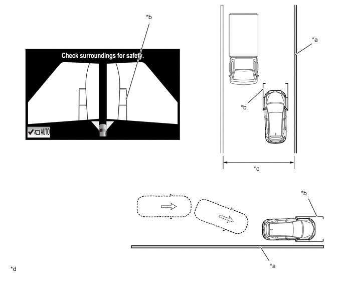
*a Wall, Fence, etc. *b Vehicle Width Parallel Line *c Narrow Road, etc *d The illustrations shown are examples only. The illustrations may differ from the actual vehicle screens.
-
-
-
Moving View
-
This view combines images from the front, rear, left and right side television camera assemblies to display an image of the vehicle from a viewpoint diagonally above the vehicle. The displayed image rotates 360 degrees around the vehicle displayed on the screen to assist with confirming the safety of the surroundings. Furthermore, after the image of the vehicle from a viewpoint diagonally above the vehicle rotates a full 360 degrees, an overhead view of the vehicle is displayed.
-
Using the rotation pause button, the rotation of the moving view can be paused and unpaused at will.
-
When the outer rear view mirror assemblies are retracted, the moving view is not displayed and the side view and wide front view is displayed.
Figure 9. Moving View (to Panoramic View) Display Contents
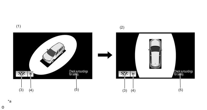
*a The illustrations shown are examples only. The illustrations may differ from the actual vehicle screens. - - Item Description (1) Moving View This function displays an image of the vehicle and its surroundings as seen from a viewpoint diagonally above the vehicle while rotating the image 360 degrees around the vehicle displayed on the screen, and then displays an overhead view of the vehicle. (2) Panoramic View Displays an overhead view from a point above the vehicle. (3) See Through View Switch Button Switches to the see through view. (4) Rotation Pause Button Pauses and unpauses the rotation of the moving view. (5) Warning Message Warns the driver according to the message on the display. Tech Tips
The color of the moving view vehicle icon can be changed. Refer to the Repair Manual for the details.
-
-
See Through View
-
See Through View (to Panoramic View) Display Contents
-
By combining the images from cameras on the front, rear, and both sides of the vehicle, a simulated video display of the area around the vehicle is created. By reducing the size of blind spots from inside the vehicle, it assists in confirming the safety of the area around the vehicle.
-
Using the rotation pause button, the rotation of the see through view can be paused andunpaused at will.
-
When the outer rear view mirror assemblies are retracted, the see through view is not displayed and the side view and wide front view is displayed.
Figure 10. See Through View (to Panoramic View) Display Contents
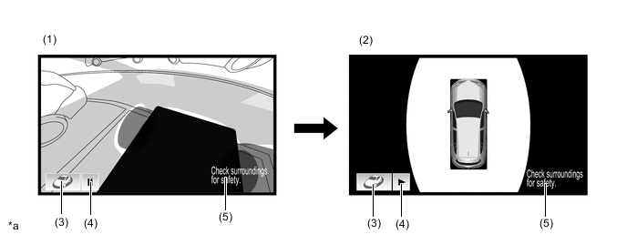
*a The illustrations shown are examples only. The illustrations may differ from the actual vehicle screens. - - Item Description (1) See Through View Simulated view of the area around the vehicle as seen from inside the vehicle. (2) Panoramic View Displays an overhead view from a point above the vehicle. (3) Moving View Switch Button Switches to the moving view. (4) Rotation Pause Button Pauses and unpauses the rotation of the see through view. (5) Warning Message Warns the driver according to the message on the display.
-
-
-
Panoramic View Monitor Screen Display Operation
-
The panoramic view monitor system has two display modes. "Manual Display Mode" displays the screen according to the needs of the driver, and "Automatic Display Mode" automatically displays the screen when the display conditions are met.
-
The panoramic view monitor screen display can be displayed and switched by operating the panoramic view monitor main switch.
-
The panoramic view monitor screen is displayed when the panoramic view monitor main switch is pressed in manual display mode or the automatic display mode display conditions are met.
-
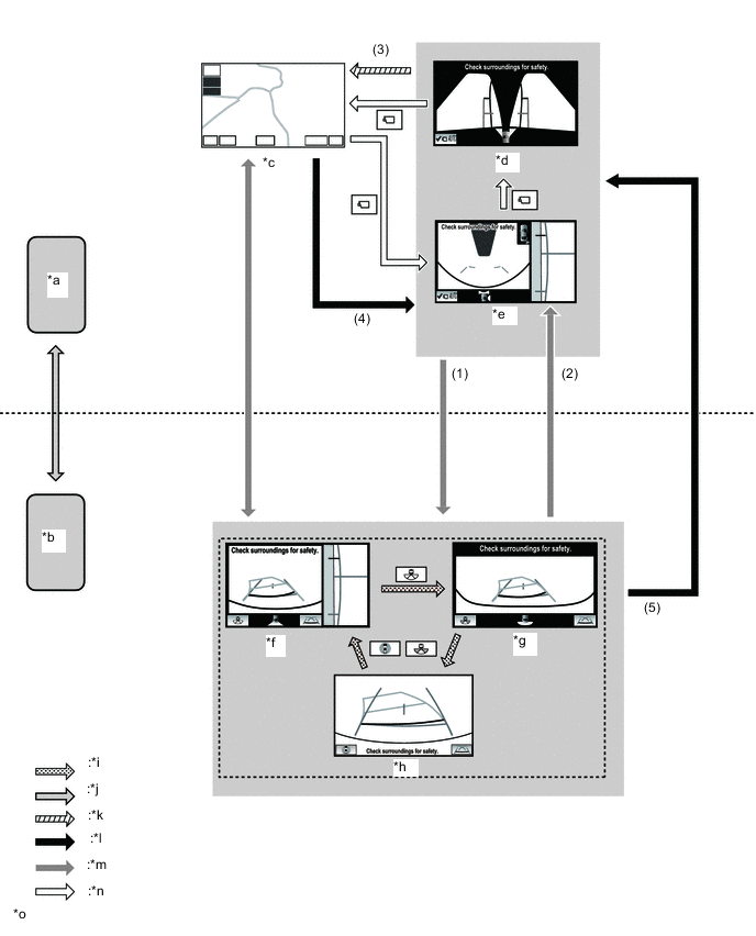
When the ignition switch is ON and the shift lever is in R, the "panoramic view and rear view screen" is displayed regardless of the operation status of the panoramic view monitor main switch.
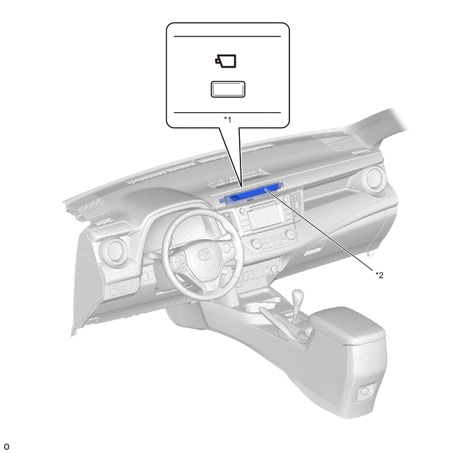
*1 Panoramic View Monitor Main Switch *2 Telltale Light Assembly
-
-
Panoramic View Monitor Screen Transition (Models with Automatic Transaxle or CVT)
-
The panoramic view monitor assists with confirming the conditions around the vehicle, driving at low speeds and driving when parking with the following screen transitions.
Figure 11. Screen Transition Chart (when Outer Rear View Mirror Assemblies are Extended)
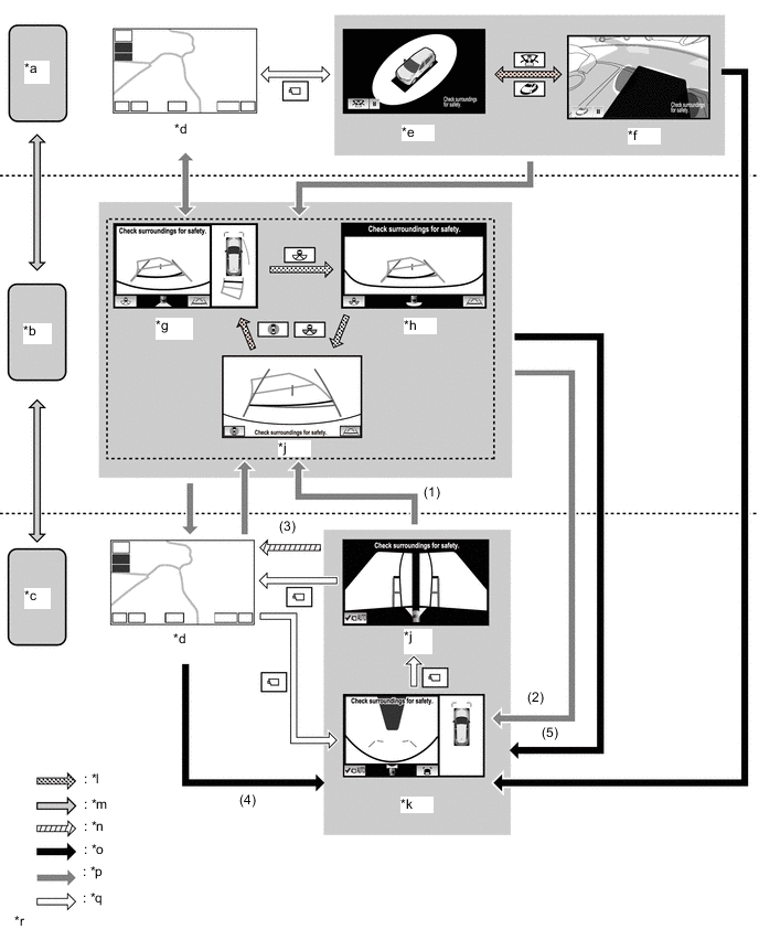
*a Shift Lever is P *b Shift Lever is in R *c Shift Lever is not in P or R *d Navigation Display etc. *e Moving View *f See Through View *g Panoramic View and Rear View *h Wide Rear View *i Rear View *j Side Simultaneous View *k Panoramic View and Wide Front View *l Screen Transition according to Priority Screen Switching *m Shift Operation *n Screen Transition according to Change in Vehicle Speed *o Screen Transition in Automatic Display Mode *p Screen Transition according to Shift Operation (Manual Display Mode) *q Screen Transition according to Switch Operation (Manual Display Mode) *r The illustrations shown are examples only. The illustrations may differ from the actual vehicle screens. Screen Transition Conditions No. Conditions (1) When the shift lever is moved while the "panoramic view and wide front view screen" or "side simultaneous view screen" is displayed after the panoramic view monitor main switch is pressed. (2) When the shift lever is moved while the "panoramic view and rear view screen", "wide rear view screen" or "rear view screen" is displayed following condition (1) (3) The vehicle speed has reached approximately 20 km/h (12.4 mph) or more. (4) When the vehicle speed becomes approximately 10 km/h (6 mph) or less (previously displayed "panoramic view and wide front view screen" or "side simultaneous view screen" is displayed) (5) When the previously displayed "panoramic view and wide front view screen" or "side simultaneous view screen" is displayed Figure 12. Screen Transition Chart (when Outer Rear View Mirror Assemblies are Retracted)
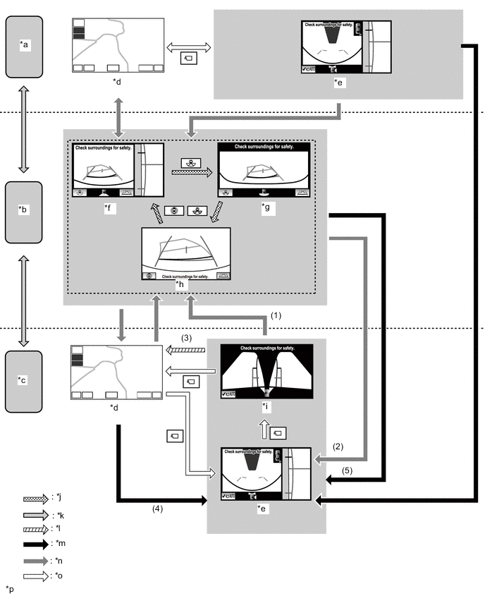
*a Shift Lever is P *b Shift Lever is in R *c Shift Lever is not in P or R *d Navigation Display etc. *e Side and Wide Front View *f Side and Rear View *g Wide Rear View *h Rear View *i Side Simultaneous View *j Screen Transition according to Priority Screen Switching *k Shift Operation *l Screen Transition according to Change in Vehicle Speed *m Screen Transition in Automatic Display Mode *n Screen Transition according to Shift Operation (Manual Display Mode) *o Screen Transition according to Switch Operation (Manual Display Mode) *p The illustrations shown are examples only. The illustrations may differ from the actual vehicle screens. Screen Transition Conditions No. Conditions (1) When the shift lever is moved while the "side and wide front view screen" or "side simultaneous view screen" is displayed after the panoramic view monitor main switch is pressed. (2) When the shift lever is moved while the "side and rear view screen", "wide rear view screen" or "rear view screen" is displayed following condition (1). (3) The vehicle speed has reached approximately 20 km/h (12.4 mph) or more. (4) When the vehicle speed becomes approximately 10 km/h (6 mph) or less (previously displayed "side view and wide front view screen" or "side simultaneous view screen" is displayed) (5) When the previously displayed "side view and wide front view screen" or "side simultaneous view screen" is displayed
-
-
Panoramic View Monitor Screen Transition (Models with Manual Transaxle)
-
The panoramic view monitor assists with confirming the conditions around the vehicle, driving at low speeds and driving when parking with the following screen transitions.
Figure 13. Screen Transition Chart (when Outer Rear View Mirror Assemblies are Extended)
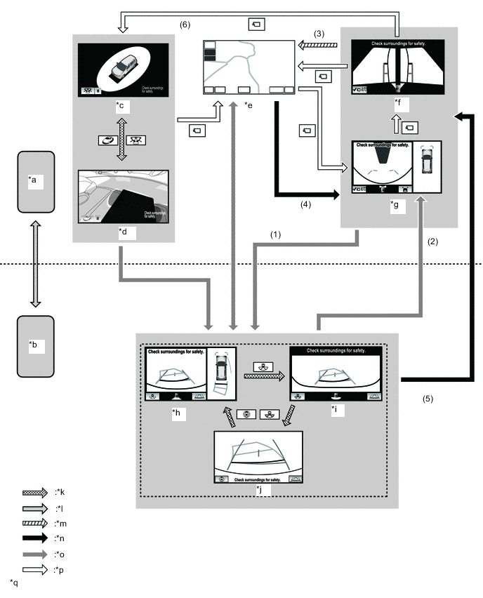
*a Except Shift Lever is in R *b Shift Lever is in R *c Moving View *d See Through View *e Navigation Display etc. *f Side Simultaneous View *g Panoramic View and Wide Front View *h Panoramic View and Rear View *i Wide Rear View *j Rear View *k Screen Transition according to Priority Screen Switching *l Shift Operation *m Screen Transition according to Change in Vehicle Speed *n Screen Transition in Automatic Display Mode *o Screen Transition according to Shift Operation (Manual Display Mode) *p Screen Transition according to Switch Operation (Manual Display Mode) *q The illustrations shown are examples only. The illustrations may differ from the actual vehicle screens. - - Screen Transition Conditions No. Conditions (1) When the shift lever is moved while the "panoramic view and wide front view screen" or "side simultaneous view screen" is displayed after the panoramic view monitor main switch is pressed. (2) When the shift lever is moved while the "panoramic view and rear view screen", "wide rear view screen" or "rear view screen" is displayed following condition (1) (3) The vehicle speed has reached approximately 20 km/h (12.4 mph) or more. (4) When the vehicle speed becomes approximately 10 km/h (6 mph) or less (previously displayed "panoramic view and wide front view screen" or "side simultaneous view screen" is displayed) (5) When the previously displayed "panoramic view and wide front view screen" or "side simultaneous view screen" is displayed (6) When the vehicle speed is 0 km/h (0 mph) and parking brake switch signal is ON Figure 14. Screen Transition Chart (when Outer Rear View Mirror Assemblies are Retracted)
*a Except Shift Lever is in R *b Shift Lever is in R *c Navigation Display etc. *d Side Simultaneous View *e Side and Wide Front View *f Side and Rear View *g Wide Rear View *h Rear View *i Screen Transition according to Priority Screen Switching *j Shift Operation *k Screen Transition according to Change in Vehicle Speed *l Screen Transition in Automatic Display Mode *m Screen Transition according to Shift Operation (Manual Display Mode) *n Screen Transition according to Switch Operation (Manual Display Mode) *o The illustrations shown are examples only. The illustrations may differ from the actual vehicle screens. - - Screen Transition Conditions No. Conditions (1) When the shift lever is moved while the "side and wide front view screen" or "side simultaneous view screen" is displayed after the panoramic view monitor main switch is pressed. (2) When the shift lever is moved while the "side and rear view screen", "wide rear view screen" or "rear view screen" is displayed following condition (1). (3) The vehicle speed has reached approximately 20 km/h (12.4 mph) or more. (4) When the vehicle speed becomes approximately 10 km/h (6 mph) or less (previously displayed "side view and wide front view screen" or "side simultaneous view screen" is displayed) (5) When the previously displayed "side view and wide front view screen" or "side simultaneous view screen" is displayed
-
-
Panoramic View Zoom Function
-
By touching the panoramic view screen, part of the panoramic view vehicle icon can be enlarged.
-
Using the zoom function, 4 areas near the vehicle corners can be enlarged.
*a Panoramic View Zoom Display *b The illustration shown is example only. The illustration may differ from the actual vehicle screen.
-
-
-
DIAGNOSIS
-
The parking assist ECU is equipped with a diagnosis function which can display a diagnosis menu for the parking assist monitor system. For details, refer to the Repair Manual.
-