ENGINE ASSEMBLY INSTALLATION

PROCEDURE
-
REMOVE ENGINE FROM ENGINE STAND
-
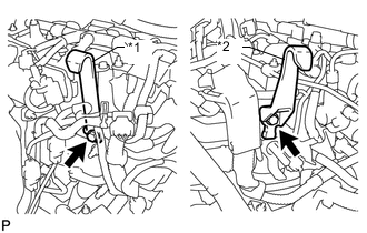
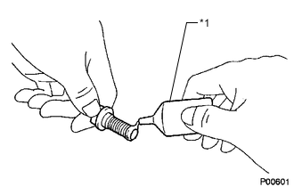
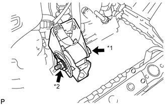
Text in Illustration *1 No. 1 Engine Hanger *2 No. 2 Engine Hanger Install the No. 1 and No. 2 engine hangers with 2 bolts as shown in the illustration.
- Torque:
- 40 N*m { 408 kgf*cm, 30 ft.*lbf }
Tech Tips
Part No. No. 1 engine hanger 12281-26040 No. 2 engine hanger 12282-26010 Bolt 91552-81025 or 90105-W0042
-
Insert the claw of the No. 1 engine hanger into the hole of the cylinder head.
-
Fit the fork part of the No. 2 engine hanger onto the rib of the cylinder head.
-
Install a sling device and chain block to the engine and hang the engine.
-
Remove the engine from the engine stand.
-
-
INSTALL FLYWHEEL SUB-ASSEMBLY (for Manual Transaxle)
-
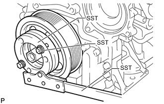
Hold the crankshaft pulley with SST.
- SST
- 09213-58014 ( 91551-80840 )
- 09330-00021
-
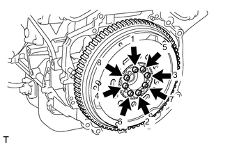
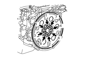
Using a T55 "TORX" socket wrench, install the flywheel with 8 new bolts and uniformly tighten the bolts in several steps in the sequence shown in the illustration.
- Torque:
- 71 N*m { 720 kgf*cm, 52 ft.*lbf }
Note
-
Do not reuse the flywheel installation bolts.
-
Be sure to check the tightening torque within 5 minutes after tightening.
-
Do not impact or damage the flywheel installation bolts. Be sure to handle them carefully.
-
Make sure there is no oil on the bolts.
Tech Tips
Make sure that the seating surface of the flywheel installation bolts and installation surfaces of the crankshaft and flywheel are free from oil and foreign matter.
-
-
INSTALL DRIVE PLATE AND RING GEAR SUB-ASSEMBLY (for Automatic Transaxle)
-
Hold the crankshaft pulley with SST.
- SST
- 09213-58014 ( 91551-80840 )
- 09330-00021
-
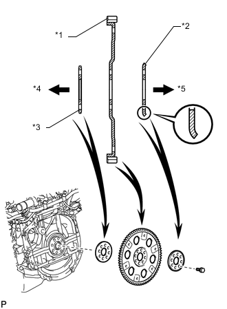
Text in Illustration *1 Drive Plate and Ring Gear *2 Rear Drive Plate Spacer *3 Front Drive Plate Spacer
(Reversible)
*4 Engine Side *5 Transaxle Side Install the front drive plate spacer, drive plate and ring gear and rear drive plate spacer to the crankshaft.
Tech Tips
-
The front drive plate spacer is reversible.
-
As the rear drive plate spacer and drive plate and ring gear are not reversible, be sure to install them in the direction show in the illustration.
-
-
Text in Illustration *1 Adhesive Apply adhesive to 2 or 3 threads of the end of the bolts.
Adhesive Toyota Genuine Adhesive 1324, Three Bond 1324 or equivalent -
Uniformly install and tighten the 8 bolts in several passes, in the sequence shown in the illustration.
- Torque:
- 92 N*m { 938 kgf*cm, 68 ft.*lbf }
-
-
INSTALL CLUTCH DISC ASSEMBLY (for Manual Transaxle)
-
INSTALL CLUTCH COVER ASSEMBLY (for Manual Transaxle)
-
INSPECT AND ADJUST CLUTCH COVER ASSEMBLY (for Manual Transaxle)
-
INSTALL MANUAL TRANSAXLE ASSEMBLY (for Manual Transaxle)
-
INSTALL AUTOMATIC TRANSAXLE ASSEMBLY (for Automatic Transaxle)
-
INSTALL STIFFENER PLATE LH
-
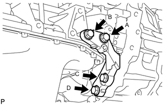
Temporarily install the stiffener plate LH with the 4 bolts.
-
While holding the stiffener plate LH against the transaxle, tighten bolt A, and then tighten bolts B, C and D.
- Torque:
- 46 N*m { 469 kgf*cm, 34 ft.*lbf }
-
-
INSTALL STIFFENER PLATE RH
-
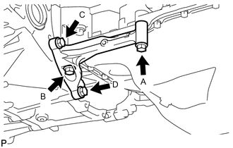
Temporarily install the stiffener plate RH with the 4 bolts.
-
While holding the stiffener plate RH against the transaxle, tighten bolt A, and then tighten bolts B, C and D.
- Torque:
- 46 N*m { 469 kgf*cm, 34 ft.*lbf }
-
-
INSTALL OIL PAN INSULATOR
-
Install the oil pan insulator with the 2 bolts.
- Torque:
- 9.0 N*m { 92 kgf*cm, 80 in.*lbf }
-
-
INSTALL ENGINE MOUNTING INSULATOR RH
Tech Tips
Perform this procedure only when replacement of the engine mounting insulator is necessary.
-
Install the engine mounting insulator RH with the 3 bolts.
- Torque:
- 95 N*m { 969 kgf*cm, 70 ft.*lbf }
-
-
INSTALL ENGINE MOUNTING INSULATOR LH
Tech Tips
Perform this procedure only when replacement of the engine mounting insulator is necessary.
-
Install the engine mounting insulator LH with the 4 bolts.
- Torque:
- 95 N*m { 969 kgf*cm, 70 ft.*lbf }
-
-
INSTALL ENGINE MOUNTING BRACKET LH
Tech Tips
Perform this procedure only when replacement of the engine mounting bracket is necessary.
-
Install the engine mounting bracket LH with the 4 bolts.
- Torque:
- 64 N*m { 653 kgf*cm, 47 ft.*lbf }
-
-
INSTALL REAR ENGINE MOUNTING BRACKET (for Manual Transaxle)
-
Install the rear engine mounting bracket with the 5 bolts.
- Torque:
- 45 N*m { 459 kgf*cm, 33 ft.*lbf }
-
-
INSTALL REAR ENGINE MOUNTING BRACKET (for Automatic Transaxle)
-
Install the rear engine mounting bracket with the 4 bolts.
- Torque:
- 45 N*m { 459 kgf*cm, 33 ft.*lbf }
-
-
INSTALL FRONT ENGINE MOUNTING BRACKET (for Manual Transaxle)
-
Install the front engine mounting bracket with the 3 bolts.
- Torque:
- 64 N*m { 653 kgf*cm, 47 ft.*lbf }
-
-
INSTALL FRONT ENGINE MOUNTING BRACKET (for Automatic Transaxle)
-
Install the front engine mounting bracket with the 4 bolts.
- Torque:
- 64 N*m { 653 kgf*cm, 47 ft.*lbf }
-
-
INSTALL ENGINE WIRE
-
INSTALL STARTER ASSEMBLY (for VALEO Made)
-
INSTALL STARTER ASSEMBLY (for DENSO Made)
-
INSTALL NO. 1 AIR TUBE
-
Install the No. 1 air tube with the 2 bolts and tighten the clamp.
- Torque:
- for bolt
- 20 N*m { 204 kgf*cm, 15 ft.*lbf }
- for clamp
- 6.5 N*m { 66 kgf*cm, 58 in.*lbf }
Note
Before installation, remove any oil residue from the inside of the tube and hose.
-
-
INSTALL REAR ENGINE MOUNTING INSULATOR
-
Install the rear engine mounting insulator with the 3 bolts and 2 nuts.
- Torque:
- 95 N*m { 969 kgf*cm, 70 ft.*lbf }
-
-
INSTALL ENGINE WITH TRANSAXLE
-
Place the engine on an engine lifter, and then remove the sling device and chain block from the engine.
Tech Tips
Place the engine on wooden blocks or equivalent so that the engine is level.
-
Using the engine lifter, slowly raise the engine and install it to the vehicle, and then install the intermediate shaft to the pinion.
CAUTION:
Do not raise the engine more than necessary. If the engine is raised excessively, the vehicle may also be lifted up.
Note
-
Make sure that the engine is clear of all wiring and hoses.
-
While raising the engine into the vehicle, do not allow it to contact the vehicle.
-
Align the matchmarks on the intermediate shaft and pinion.
-
-
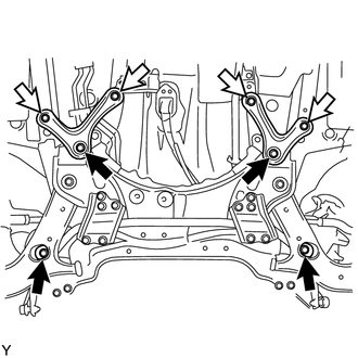
Temporarily install the suspension crossmember with 2 new bolts.
Text in Illustration 
New Bolt 
Bolt -
Temporarily install the rear brace RH and LH with 2 new bolts and the 4 bolts.
-
Connect the engine mounting insulator LH with the bolt and nut.
- Torque:
- 56 N*m { 571 kgf*cm, 41 ft.*lbf }
Tech Tips
While holding the bolt in place, tighten the nut.
-
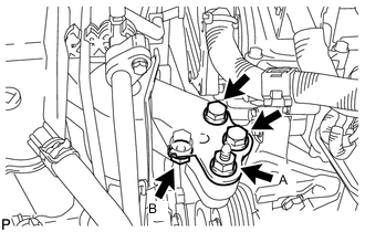
Connect the engine mounting insulator RH with the 2 bolts and 2 nuts.
- Torque:
- for bolt, nut A
- 95 N*m { 969 kgf*cm, 70 ft.*lbf }
- for nut B
- 52 N*m { 530 kgf*cm, 38 ft.*lbf }
-
Tighten the 8 bolts.
- Torque:
- for bolt A
- 137 N*m { 1397 kgf*cm, 101 ft.*lbf }
- for bolt B
- 93 N*m { 948 kgf*cm, 69 ft.*lbf }
-
Remove the 2 bolts and No. 1 and No. 2 engine hangers.
-
Attach the 3 clamps and connect the wire harness.
-
Connect the cable bracket with the bolt.
- Torque:
- 5.0 N*m { 51 kgf*cm, 44 in.*lbf }
-
-
INSTALL FRONT ENGINE MOUNTING INSULATOR
-
Text in Illustration *1 Through Bolt *2 Nut Install the front engine mounting insulator with the through bolt and nut.
- Torque:
- 145 N*m { 1479 kgf*cm, 107 ft.*lbf }
-
-
INSTALL FRONT CROSSMEMBER SUB-ASSEMBLY
-
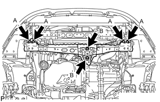
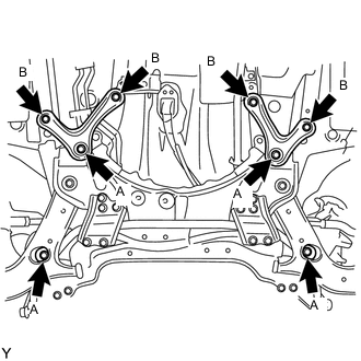
Install the front crossmember with the 6 bolts.
- Torque:
- for bolt A
- 99 N*m { 1010 kgf*cm, 73 ft.*lbf }
- for bolt B
- 95 N*m { 969 kgf*cm, 70 ft.*lbf }
-
-
INSTALL FRONT SUSPENSION MEMBER REINFORCEMENT LH
-
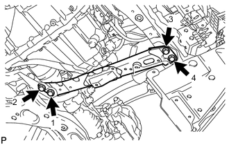
Install the front suspension member reinforcement LH with the 4 bolts.
- Torque:
- 99 N*m { 1010 kgf*cm, 73 ft.*lbf }
Note
Tighten the bolts in the order shown in the illustration.
-
-
INSTALL FRONT DRIVE SHAFT ASSEMBLY LH
-
INSTALL FRONT DRIVE SHAFT ASSEMBLY RH
-
INSTALL FRONT AXLE ASSEMBLY LH
-
INSTALL FRONT AXLE ASSEMBLY RH
-
CONNECT FRONT STABILIZER LINK ASSEMBLY LH
-
CONNECT FRONT STABILIZER LINK ASSEMBLY RH
Tech Tips
Perform the same procedure as for the LH side.
-
INSTALL FRONT AXLE SHAFT NUT LH
-
INSTALL FRONT AXLE SHAFT NUT RH
Tech Tips
Perform the same procedure as for the LH side.
-
INSTALL NO. 1 STEERING COLUMN HOLE COVER SUB-ASSEMBLY
-
CONNECT NO. 2 STEERING INTERMEDIATE SHAFT ASSEMBLY
-
INSTALL COLUMN HOLE COVER SILENCER SHEET
-
CONNECT CLUTCH RELEASE CYLINDER ASSEMBLY (for Manual Transaxle)
-
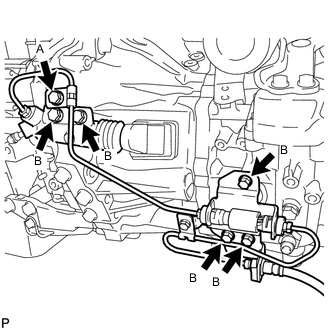
Connect the clutch release cylinder and flexible hose bracket with the 6 bolts.
- Torque:
- for bolt A
- 8.0 N*m { 82 kgf*cm, 71 in.*lbf }
- for bolt B
- 12 N*m { 122 kgf*cm, 9 ft.*lbf }
-
-
CONNECT TRANSMISSION CONTROL CABLE ASSEMBLY (for Manual Transaxle)
-
Connect the transmission control cable to the control cable bracket with 2 new clips.
-
Install the 2 pins.
-
-
CONNECT TRANSMISSION CONTROL CABLE ASSEMBLY (for Automatic Transaxle)
-
Connect the transmission control cable with the nut and new clip.
- Torque:
- 12 N*m { 122 kgf*cm, 9 ft.*lbf }
-
-
CONNECT COMPRESSOR WITH PULLEY ASSEMBLY (w/ Air Conditioning System)
-
Using an E8 "TORX" socket wrench, connect the compressor with the 2 stud bolts.
- Torque:
- 9.8 N*m { 100 kgf*cm, 87 in.*lbf }
-
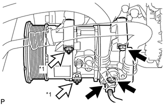
Text in Illustration *1 Nut Install the 2 bolts and 2 nuts.
- Torque:
- 25 N*m { 255 kgf*cm, 18 ft.*lbf }
-
Connect the connector.
-
-
INSTALL FAN AND GENERATOR V BELT
-
INSTALL FRONT SUSPENSION MEMBER REINFORCEMENT RH
-
INSTALL INJECTOR DRIVER (for Manual Transaxle)
-
Install the injector driver with the 3 screws.
- Torque:
- 6.0 N*m { 61 kgf*cm, 53 in.*lbf }
-
Attach the clamp and connect the 4 connectors.
-
-
CONNECT NO. 2 RADIATOR HOSE (for Manual Transaxle)
-
Connect the No. 2 radiator hose.
-
-
CONNECT WATER BY-PASS HOSE
-
Connect the water by-pass hose.
-
-
INSTALL INTERCOOLER AIR HOSE (for Manual Transaxle)
-
CONNECT NO. 1 RADIATOR HOSE (for Manual Transaxle)
-
Connect the No. 1 radiator hose.
-
-
CONNECT INLET HEATER WATER HOSE
-
Connect the inlet heater water hose.
-
-
CONNECT OUTLET HEATER WATER HOSE
-
Connect the outlet heater water hose.
-
-
CONNECT HOSES AND CONNECTORS
-
Connect the vacuum pump hose.
-
Connect the 2 fuel hoses.
-
for Manual Transaxle:
Attach the 4 clamps and connect the wire harness.
-
for Automatic Transaxle:
Connect the TCM connector.
-
for Manual Transaxle:
Connect the ground cable with the bolt.
- Torque:
- 13 N*m { 127 kgf*cm, 9 ft.*lbf }
-
for Automatic Transaxle:
Connect the ground cable with the bolt and attach the clamp.
- Torque:
- 13 N*m { 131 kgf*cm, 9 ft.*lbf }
-
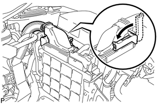
Connect the 3 connectors, attach the 2 claws to install the No. 1 engine room relay block and install the 2 nuts.
- Torque:
- 8.4 N*m { 86 kgf*cm, 74 in.*lbf }
-
Connect the current sensor connector.
-
Install the engine room No. 1 relay block cover.
-
-
INSTALL AIR CLEANER BRACKET
-
Install the air cleaner bracket with the 3 bolts.
- Torque:
- 7.0 N*m { 71 kgf*cm, 62 in.*lbf }
-
-
INSTALL FUEL FILTER SUPPORT
-
Install the fuel filter support with the 3 bolts.
- Torque:
- 18 N*m { 178 kgf*cm, 13 ft.*lbf }
-
Attach the 2 clamps and connect the wire harness.
-
Connect the glow relay with the bolt.
- Torque:
- 18 N*m { 178 kgf*cm, 13 ft.*lbf }
-
Attach the 2 clamps and connect the engine wire.
-
Connect the connector.
-
Connect the ECM connector and lower the lever.
Note
-
When connecting the connector, make sure that dirt, water and other foreign matter is not stuck between the connector and ECM.
-
Make sure that the lever is securely lowered.
-
-
-
INSTALL FUEL FILTER ASSEMBLY (w/o Combustion Type Power Heater)
-
INSTALL FUEL FILTER ASSEMBLY (w/ Combustion Type Power Heater)
-
INSTALL AIR CLEANER CASE
-
Install the air cleaner case with the 3 bolts.
- Torque:
- 7.0 N*m { 71 kgf*cm, 62 in.*lbf }
-
-
INSTALL AIR CLEANER FILTER ELEMENT SUB-ASSEMBLY
-
INSTALL AIR CLEANER CAP SUB-ASSEMBLY
-
Connect the air cleaner hose.
-
Attach the 4 clamps to install the air cleaner cap.
-
Connect the No. 2 ventilation hose.
-
Attach the clamp and connect the mass air flow meter connector.
-
-
INSTALL NO. 3 AIR HOSE
-
CONNECT NO. 2 VACUUM TRANSMITTING HOSE ASSEMBLY
-
Connect the No. 2 vacuum transmitting hose to the intake manifold.
-
-
INSTALL OIL COOLER TUBE SUB-ASSEMBLY (for Automatic Transaxle)
-
Install the oil cooler tube with the bolt.
- Torque:
- 12 N*m { 122 kgf*cm, 9 ft.*lbf }
-
Connect the 2 hoses.
-
-
INSTALL RADIATOR ASSEMBLY (for Automatic Transaxle)
-
INSTALL BATTERY CARRIER
-
INSTALL BATTERY TRAY
-
INSTALL BATTERY
-
INSTALL BATTERY INSULATOR
-
INSTALL BATTERY CLAMP SUB-ASSEMBLY
-
INSTALL FRONT EXHAUST PIPE ASSEMBLY
-
ADD MANUAL TRANSAXLE OIL (for Manual Transaxle)
-
ADD ENGINE OIL
-
INSTALL FRONT BUMPER COVER (for Automatic Transaxle)
-
INSTALL OUTER COWL TOP PANEL SUB-ASSEMBLY
-
Install the outer cowl top panel with the 9 bolts.
- Torque:
- 8.8 N*m { 90 kgf*cm, 78 in.*lbf }
-
Attach the clamp and connect the connector.
-
-
INSTALL DIFFERENTIAL PRESSURE SENSOR ASSEMBLY
-
INSTALL FRONT WIPER MOTOR AND LINK ASSEMBLY
-
INSTALL FRONT WHEEL
-
CONNECT CABLE TO POSITIVE BATTERY TERMINAL
-
CONNECT CABLE TO NEGATIVE BATTERY TERMINAL
Note
When disconnecting the cable, some systems need to be initialized after the cable is reconnected Click here.
-
BLEED FUEL SYSTEM
-
ADD ENGINE COOLANT
-
ADD AUTOMATIC TRANSAXLE FLUID (for Automatic Transaxle)
-
PERFORM REGISTRATION
-
Perform registration of the injector compensation codes Click here.
-
Perform registration of the pilot quantity learning Click here.
-
-
PERFORM INITIALIZATION
-
Perform initialization of the crank time compensation reset function Click here.
-
-
PERFORM THROTTLE VALVE FULLY CLOSED POSITION LEARNING
-
INSPECT FOR OIL LEAK
-
INSPECT FOR COOLANT LEAK
-
INSPECT FOR FUEL LEAK
-
INSPECT FOR EXHAUST GAS LEAK
-
INSTALL RADIATOR SUPPORT OPENING COVER
-
INSTALL NO. 1 ENGINE COVER
-
INSTALL REAR ENGINE UNDER COVER RH
-
INSTALL REAR ENGINE UNDER COVER LH
-
Install the rear engine under cover LH with the 5 clips.
-
-
INSTALL NO. 2 ENGINE UNDER COVER
-
INSTALL CENTER NO. 4 ENGINE UNDER COVER
-
Install the center No. 4 engine under cover with the 2 clips.
-
-
INSTALL NO. 1 ENGINE UNDER COVER
-
INSTALL FRONT LOWER BUMPER ABSORBER
-
CHECK IDLE SPEED
-
CHECK MAXIMUM ENGINE SPEED
-
ADJUST FRONT WHEEL ALIGNMENT
-
CHECK ABS SPEED SENSOR SIGNAL
-
PERFORM CLUTCH ENGAGEMENT POINT LEARNING (for Manual Transaxle)