ДВИГАТЕЛЬ В СБОРЕ УСТАНОВКА

-
INSTALL ENGINE WIRE
-
Install the engine wire to the engine assembly.
-
-
INSTALL ENGINE HANGERS
-
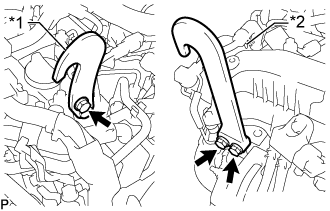
Text in Illustration *1 Upper No. 1 Engine Hanger *2 No. 2 Engine Hanger Install the upper No. 1 engine hanger and No. 2 engine hanger with the 3 bolts as shown in the illustration.
- Torque:
- for upper No. 1 engine hanger
- 29 N*m { 296 kgf*cm, 21 ft.*lbf }
- for No. 2 engine hanger
- 26 N*m { 265 kgf*cm, 19 ft.*lbf }
Note
Install the engine hangers with new bolts.
Tech Tips
Upper No. 1 Engine Hanger 12284-11010 or 12284-11020 No. 2 Engine Hanger 12282-11080 or 12282-11090 Bolt 91552-81025 and 91672-80835 -
Attach an engine sling device and hang the engine assembly with a chain block.
-
-
REMOVE ENGINE STAND
Note
-
Pay attention to the angle of the sling device as the engine assembly or engine hangers may be damaged or deformed if the angle is incorrect.
-
With the exception of installing the engine assembly to an engine stand or removing the engine assembly from an engine stand, do not perform any work on the engine assembly while it is suspended, as doing so is dangerous.
-
Attach the engine sling device and hang the engine assembly with the chain block.
-
Remove the engine assembly from the engine stand.
-
-
INSTALL FRONT ENGINE MOUNTING INSULATOR
-
Install the 2 front engine mounting insulators and 2 engine mounting stabilizers with the 2 nuts.
- Torque:
- 64 N*m { 653 kgf*cm, 47 ft.*lbf }
-
-
INSTALL FRONT ENGINE MOUNTING INSULATOR RH
-
Install the front engine mounting insulator RH to the engine mounting stabilizer with the nut.
- Torque:
- 8.0 N*m { 82 kgf*cm, 71 in.*lbf }
-
-
INSTALL FRONT SUSPENSION CROSSMEMBER SUB-ASSEMBLY
-
Install the front suspension crossmember sub-assembly to the engine assembly with the 4 bolts.
- Torque:
- 55 N*m { 561 kgf*cm, 41 ft.*lbf }
-
-
INSTALL ENGINE ASSEMBLY
-
Set an engine lifter in place.
-
Remove the engine sling device and chain block.
-
Remove the 2 bolts and 2 engine hangers.
-
Operate the engine lifter and install the engine to the vehicle.
-
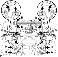
Install the engine with crossmember with the 16 bolts.
- Torque:
- for bolt A
- 39 N*m { 398 kgf*cm, 29 ft.*lbf }
- for bolt B
- 36 N*m { 367 kgf*cm, 27 ft.*lbf }
- for bolt C
- 150 N*m { 1530 kgf*cm, 111 ft.*lbf }
-
Remove the engine lifter.
-
-
INSTALL NO. 2 ENGINE COVER
-
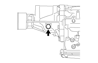
Install the No. 2 engine cover to the No. 1 engine hanger.
-
-
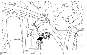
CONNECT STEERING TORQUE SHAFT ASSEMBLY
-
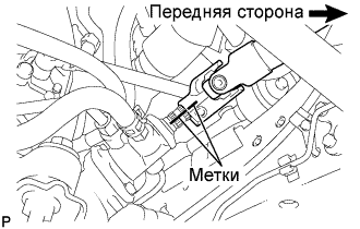
Совместите метки на крутящем валу рулевого управления в сборе и тяге рулевого управления с усилителем в сборе.
-
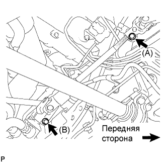
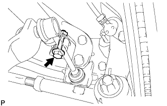
Вверните болт (B) и затяните 2 болта.
- Torque:
- 35 Н*м { 360 кгс*см, 26 фунт-сила-футов }
-
-
CONNECT FRONT SHOCK ABSORBER ASSEMBLY LH
-
CONNECT FRONT SHOCK ABSORBER ASSEMBLY RH
Tech Tips
Use the same procedure described for the LH side.
-
CONNECT FRONT SUSPENSION ARM SUB-ASSEMBLY UPPER LH
-
Подсоедините верхний рычаг передней подвески к поворотному кулаку и закрепите гайкой.
- Torque:
- 113 Н*м { 1 150 кгс*см, 83 фунт-сила-фута }
-
Установите новый шплинт.
Note
-
Если отверстия под шплинт не совпадают, затяните гайку на угол до 60°.
-
Старайтесь не повредить пыльник шарового шарнира.
-
-
-
CONNECT FRONT SUSPENSION ARM SUB-ASSEMBLY UPPER RH
Tech Tips
Use the same procedure described for the LH side.
-
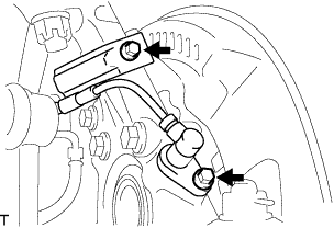
CONNECT FRONT DISC BRAKE CALIPER ASSEMBLY LH
-
Установите суппорт тормоза в сборе на поворотный кулак и закрепите 2 болтами.
- Torque:
- 123 Н*м { 1 250 кгс*см, 91 фунт-сила-фут }
-
-
CONNECT FRONT DISC BRAKE CALIPER ASSEMBLY RH
Tech Tips
Use the same procedure described for the LH side.
-
CONNECT FRONT SPEED SENSOR LH
-
Установите датчик частоты вращения на поворотный кулак и закрепите его 2 болтами.
- Torque:
- 8,5 Н*м { 87 кгс*см, 75 фунт-сила-дюймов }
Note
-
Не допускайте налипания на датчик частоты вращения посторонних частиц.
-
Будьте осторожны, чтобы не повредить датчик частоты вращения.
-
Не допускайте перекручивания провода датчика частоты вращения при установке.
-
-
CONNECT FRONT SPEED SENSOR RH
Tech Tips
Use the same procedure described for the LH side.
-
INSTALL REAR END PLATE
-
Install the rear end plate to the cylinder block sub-assembly with the bolt.
- Torque:
- 10 N*m { 102 kgf*cm, 7 ft.*lbf }
-
-
INSTALL FLYWHEEL SUB-ASSEMBLY
-
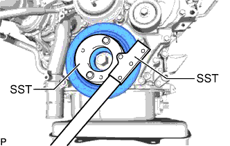
Using SST, hold the crankshaft pulley.
- SST
- 09213-58014 ( 91551-80840 )
- 09330-00021
-
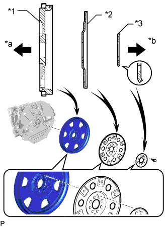
Text in Illustration *1 Flywheel Sub-assembly *2 Pump Impeller Drive Plate *3 Rear Drive Plate Spacer *a Engine Side *b Transmission Side Install the flywheel sub-assembly, the pump impeller drive plate and the rear drive plate spacer to the crankshaft with the 8 bolts.
Note
-
Align either hole in the pump impeller drive plate and either hole in the rear drive plate spacer with the knock pin of the flywheel sub-assembly, and then install the flywheel sub-assembly, the pump impeller drive plate and the rear drive plate spacer to the crankshaft.
-
Do not start the engine for at least 1 hour after installation.
Tech Tips
As the rear drive plate spacer and pump impeller drive plate are not reversible, be sure to install them in the direction shown in the illustration.
-
-
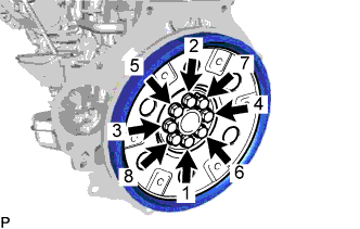
Install and uniformly tighten and tighten the 8 bolts in several steps in the sequence shown in the illustration.
- Torque:
- 178 N*m { 1815 kgf*cm, 131 ft.*lbf }
-
Install the crankshaft pulley cover to the crankshaft pulley with the 4 bolts.
- Torque:
- 21 N*m { 214 kgf*cm, 15 ft.*lbf }
-
-
INSTALL AUTOMATIC TRANSMISSION ASSEMBLY
-
INSTALL DRIVE PLATE AND TORQUE CONVERTER CLUTCH SETTING BOLT
-
Turn the crankshaft to gain access to the installation locations of the 6 drive plate and torque converter setting bolts and install each bolt while holding the crankshaft pulley bolt with a wrench.
- Torque:
- 48 N*m { 489 kgf*cm, 35 ft.*lbf }
Note
Install the black colored bolt first, and then the 5 silver colored bolts.
-
-
INSTALL PROPELLER SHAFT ASSEMBLY
-
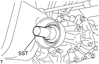
Снимите SST с удлинителя картера трансмиссии.
-
Установите карданный вал в сборе в удлинитель картера трансмиссии.
-
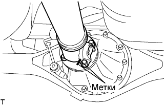
Совместите метки на фланце карданного вала и фланце дифференциала.
-
Закрепите карданный вал в сборе с помощью 4 гаек, 4 болтов и 4 шайб.
- Torque:
- 74 Н*м { 755 кгс*см, 54 фунт-сила-фута }
-
-
CONNECT NO. 4 RADIATOR HOSE
-
Connect the No. 4 radiator hose to the water inlet, and slide the clip to secure the hose.
-
-
CONNECT NO. 2 FUEL HOSE
-
Connect the No. 2 fuel hose to the No. 3 nozzle leakage pipe assembly, and slide the clamp to secure the hose.
-
-
CONNECT NO. 1 FUEL HOSE
-
Connect the No. 1 fuel hose to the No. 2 fuel pipe, and slide the clamp to secure the hose.
-
-
CONNECT VACUUM TUBE CONNECTOR HOSE
-
Connect the vacuum tube connector hose to the No. 1 hose to hose tube, and slide the clamp to secure the hose.
-
-
INSTALL INTERCOOLER AIR TUBE
-
Install the intercooler air tube to the diesel throttle body assembly.
-
Install the air tube support bracket to the intake air tube and gas filter bracket with the 2 bolts.
- Torque:
- 6.0 N*m { 62 kgf*cm, 53 in.*lbf }
-
-
CONNECT NO. 4 AIR HOSE
-
Connect the No. 4 air hose to the No. 3 air tube.
- Torque:
- 6.0 N*m { 62 kgf*cm, 53 in.*lbf }
-
Connect the oil return hose to the No. 4 air hose, and slide the clamp to secure the hose.
-
Connect the connector to the intake air temperature sensor.
-
-
CONNECT NO. 1 COOLER REFRIGERANT SUCTION HOSE
-
Снимите виниловую ленту с трубки низкого давления кондиционера № 1.
-
Нанесите необходимое количество компрессорного масла на новое кольцевое уплотнение и пригоночную поверхность компрессора системы кондиционирования.
Компрессорное масло ND-OIL 8 или аналогичное -
Установите кольцевое уплотнение на трубопровод низкого давления кондиционера № 1.
-
Подсоедините трубопровод высокого низкого № 1 к компрессору системы кондиционирования и закрепите его болтом.
- Torque:
- 9,8 Н*м { 100 кгс*см, 87 фунт-сила-дюймов }
-
-
CONNECT NO. 1 COOLER REFRIGERANT DISCHARGE HOSE
-
Снимите виниловую ленту с трубки высокого давления кондиционера № 1.
-
Нанесите необходимое количество компрессорного масла на новое кольцевое уплотнение и пригоночную поверхность компрессора системы кондиционирования.
Компрессорное масло ND-OIL 8 или аналогичное -
Установите кольцевое уплотнение на трубопровод № 1 высокого давления на выходе компрессора.
-
Подсоедините трубопровод высокого давления № 1 к компрессору системы кондиционирования и закрепите его болтом.
- Torque:
- 9,8 Н*м { 100 кгс*см, 87 фунт-сила-дюймов }
-
-
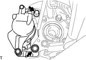
CONNECT VANE PUMP ASSEMBLY
-
Connect the vane pump assembly to the generator bracket.
- Torque:
- 21 N*m { 214 kgf*cm, 15 ft.*lbf }
-
-
CONNECT VANE PUMP OIL RESERVOIR ASSEMBLY
-
Connect the vane pump oil reservoir assembly to the body with the 2 nuts.
- Torque:
- 20 N*m { 204 kgf*cm, 15 ft.*lbf }
-
-
CONNECT NO. 1 RADIATOR HOSE
-
Connect the No. 1 radiator hose to the water outlet sub-assembly, and slide the clip to secure the hose.
-
-
CONNECT WATER BY-PASS HOSE SUB-ASSEMBLY
-
Connect the water by-pass hose sub-assembly to the water by-pass pipe, and slide the clamp to secure the hose.
-
Connect the water by-pass hose sub-assembly to the water by-pass pipe assembly, and slide the clamp to secure the hose.
-
-
CONNECT NO. 1 AIR HOSE
-
Connect the No. 1 air hose to the No. 1 air tube, and slide the clamp to secure the hose.
-
-
CONNECT AIR CLEANER HOSE ASSEMBLY
-
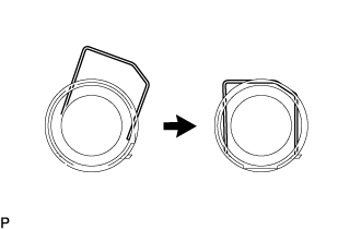
Push down the retainer of the air cleaner hose assembly as shown in the illustration.
-
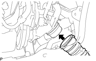
Connect the air cleaner hose assembly to the compressor inlet elbow.
Note
Check for any foreign matter on the O-ring of the air cleaner hose assembly. Clean if necessary.
-
Check that the air cleaner hose and compressor inlet elbow are securely connected by pulling on air cleaner hose assembly.
-
-
CONNECT ENGINE WIRE
-
Attach the clamp and connect the engine wire to the body.
-
Install the bolt.
- Torque:
- 9.0 N*m { 92 kgf*cm, 80 in.*lbf }
-
Connect the connector.
-
Connect the 2 connectors to the engine room main wire.
-
Attach the 2 clamps and connect the engine wire to wiring harness protector.
-
Attach the 4 claws and install the wiring harness protector cover to the wiring harness protector.
-
Install the ECM Click here.
-
-
INSTALL FRONT EXHAUST PIPE ASSEMBLY
-
INSTALL STARTER ASSEMBLY
-
INSTALL GENERATOR ASSEMBLY
-
TIGHTEN FRONT SHOCK ABSORBER ASSEMBLY LH
-
Затяните болт с нижней стороны переднего амортизатора.
- Torque:
- 105 Н*м { 1 070 кгс*см, 77 фунт-сила-футов }
-
-
TIGHTEN FRONT SHOCK ABSORBER ASSEMBLY RH
Tech Tips
Use the same procedure described for the LH side.
-
CONNECT CABLE TO NEGATIVE BATTERY TERMINAL
-
ADD ENGINE OIL
-
Залейте новое моторное масло.
Стандартный класс масла по степени вязкости Параметр / Устройство Класс масла по степени вязкости Вязкость масла (SAE) Для моделей с DPF ACEA C2
(использование моторного масла, отличного от ACEA C2, может привести к повреждению каталитического нейтрализатора)
- 0W-30
- 5W-30
Для моделей без DPF G-DLD1, API CF-4, CF или ACEA B1
(также можно использовать API CE или CD)
- 5W-30
- 10W-30
- 15W-40
- 20W-50
Стандартный объем (с DPF) Параметр / Устройство Заливаемый объем Слив и заполнение без замены масляного фильтра 6,6 л (7,0 кварты США, 5,8 английской кварты) Слив и заполнение с заменой масляного фильтра 6,8 литра (7,2 кварты США, 6,0 английской кварты) Заполнение сухой системы 7,5 л (7,9 кварты США, 6,6 английской кварты) Стандартный объем (без DPF) Параметр / Устройство Заливаемый объем Слив и заполнение без замены масляного фильтра 6,8 литра (7,2 кварты США, 6,0 английской кварты) Слив и заполнение с заменой масляного фильтра 7,0 л (7,4 кварты США, 6,2 английской кварты) Заполнение сухой системы 7,7 литра (8,1 кварты США, 6,8 английской кварты) -
Установите крышку маслоналивной горловины.
-
-
ADD ENGINE COOLANT
-
Надежно затяните сливные пробки.
-
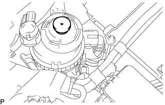
Залейте в расширительный бачок системы охлаждения охлаждающую жидкость двигателя до верха горловины.
Номинальный объем 13,9 л (14,6 кварты США, 12,2 английской кварты) Note
Не доливайте простую воду вместо охлаждающей жидкости двигателя.
Tech Tips
-
Использование неподходящей охлаждающей жидкости может привести к повреждению системы охлаждения двигателя.
-
Разрешается использовать только охлаждающую жидкость "TOYOTA Super Long Life Coolant (SLLC)" или аналогичную высококачественную охлаждающую жидкость на основе этиленгликоля (не на силикатной, аминовой, нитритной или борнокислой основе), изготовленную по гибридной технологии органических кислот с длительным сроком годности (охлаждающая жидкость, изготовленная по гибридной технологии органических кислот с длительным сроком годности, состоит из низкофосфатных соединений и органических кислот).
-
-
Ослабьте прокачной штуцер выпускного патрубка охлаждающей жидкости в сборе.
-
После удаления воздуха и слива охлаждающей жидкости двигателя надежно затяните прокачной штуцер.
- Torque:
- 8,0 Н*м { 82 кгс*см, 71 фунт-сила-дюйм }
-

Долейте охлаждающую жидкость двигателя в расширительный бачок системы охлаждения до отметки B и установите пробку радиатора.
-
Прогревайте двигатель, пока не откроется термостат.
-
Когда термостат откроется, несколько минут прокачивайте охлаждающую жидкость двигателя.
Tech Tips
Время открывания термостата можно проверить, сжав шланг радиатора № 3 рукой и определив, когда охлаждающая жидкость начинает поступать в шланг.
-
-
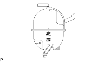
После охлаждения двигателя убедитесь, что уровень охлаждающей жидкости двигателя находится между отметками "LOW" и "FULL".
-
-
BLEED AIR FROM FUEL SYSTEM
-
Using the hand pump mounted on the fuel filter cap, bleed air from the fuel system. Continue pumping until the pump resistance increases.
Note
-
The maximum hand pump pumping speed is 2 strokes per second.
-
The hand pump must be pushed with a full stroke during pumping.
-
When the fuel pressure at the supply pump inlet port reaches a saturated pressure, the hand pump resistance increases.
-
If pumping is interrupted during the air bleeding process, fuel in the fuel line may return to the fuel tank. Continue pumping until the hand pump resistance increases.
-
If the hand pump resistance does not increase despite consecutively pumping 200 times or more, there may be a fuel leak between the fuel tank and fuel filter, the hand pump may be malfunctioning, or the vehicle may have run out of fuel.
-
If air bleeding using the hand pump is incomplete, the common rail pressure does not rise to the pressure range necessary for normal use and the engine cannot be started.
-
-
Check if the engine starts.
Note
-
Even if air bleeding using the hand pump has been completed, the starter may need to be cranked for 10 seconds or more to start the engine.
-
Do not crank the engine continuously for more than 20 seconds. The battery may be discharged.
-
Use a fully-charged battery.
-
When the engine can be started, proceed to the next step.
-
If the engine cannot be started, bleed air again using the hand pump until the hand pump resistance increases (refer to the procedures above). Then start the engine.
-
-
Turn the ignition switch off.
-
Connect the GTS to the DLC3.
-
Turn the ignition switch to ON and turn the GTS on.
-
Clear the DTCs Click here.
-
Start the engine.*1
-
Enter the following menus: Powertrain / Engine and ECT / Active Test / Test the Fuel Leak.*2
-
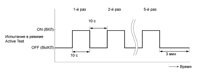
Perform the following test 5 times with on/off intervals of 10 seconds: Active Test / Test the Fuel Leak.*3
-
Allow the engine to idle for 3 minutes or more after performing the Active Test for the 5th time.
Tech Tips
When the Active Test "Test the Fuel Leak" is used to change the pump control mode, the actual fuel pressure inside the common rail drops below the target fuel pressure when the Active Test is off, but this is normal and does not indicate a pump malfunction.
-
Enter the following menus: Powertrain / Engine and ECT /Trouble Codes.
-
Read Current DTCs.
-
Clear the DTCs Click here.
Tech Tips
It is necessary to clear the DTCs as DTC P1604 or P1605 may be stored when air is bled from the fuel system after replacing or repairing fuel system parts.
-
Repeat steps *1 to *3.
-
Enter the following menus: Powertrain / Engine and ECT / Trouble Codes.
-
Read Current DTCs.
OK No DTCs are output.
-
-
CHARGE REFRIGERANT
-
Используя вакуумный насос, выполните вакуумную очистку.
-
Заправьте хладагент HFC-134a (R134a).
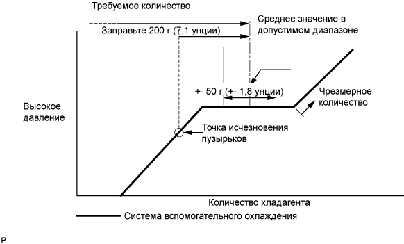
Номинальное значение Одиночный кондиционер 520-580 г (18,3-20,5 унции) Двойной кондиционер 670-730 г (23,0-25,7 унции) - SST
- 07110-58060 ( 07117-58090, 07117-78050, 07117-58070, 07117-58060, 07117-58080, 07117-88060, 07117-88070, 07117-88080 )
Note
-
Не включайте компрессор системы кондиционирования, пока не заправите ее хладагентом, иначе компрессор перегреется, поскольку без хладагента он не может функционировать правильно.
-
Приблизительно 100 г (3,5 унции) После исчезновения пузырьков может потребоваться заправить ... хладагента. В процессе заправки необходимо контролировать количество хладагента, не обращая внимания на смотровое окошко.
Tech Tips
В случае использования газообразного хладагента, собираемого с помощью устройства сбора/восстановления фреона, необходимо приготовить дополнительную тару для заправки хладагента, поскольку производительность устройства сбора составляет приблизительно 90% от расхода.
-
-
ADD AUTOMATIC TRANSMISSION FLUID
-
INSPECT FOR FUEL LEAK
Note
-
During Active Test mode, the engine speed becomes high and the combustion noise becomes loud, so pay attention.
-
During Active Test mode, the fuel pressure becomes high. Be extremely careful not to expose your eyes, hands, or body to escaping fuel.
Tech Tips
Using the GTS to perform Active Tests allow relays, VSVs, actuators and other items to be operated without removing any parts. This non-intrusive functional inspection can be very useful because intermittent operation may be discovered before parts or wiring is disturbed. Performing Active Tests early in troubleshooting is one way to save diagnostic time. Data List information can be displayed while performing Active Tests.
-
Check that there are no leaks from any part of the fuel system when the engine is stopped. If there is fuel leakage, repair or replace parts as necessary.
-
Start the engine and check that there are no leaks from any part of the fuel system. If there is fuel leakage, repair or replace parts as necessary.
-
Disconnect the return hose from the common rail assembly.
-
Start the engine and check for fuel leaks from the return pipe. If there is fuel leakage, replace the common rail assembly.
-
Perform the Active Test.
-
Connect the GTS to the DLC3.
-
Turn the ignition switch to ON.
-
Turn the GTS on.
-
Enter the following menus: Powertrain / Engine / Active Test / Test the Fuel Leak.
-
If the GTS is not available, fully depress the accelerator pedal quickly. Increase the engine speed to the maximum and maintain that speed for 2 seconds. Repeat this operation several times.
-
Check that there are no leaks from any part of the fuel system.
Tech Tips
A return pipe leakage of less than 10 cc (0.6 cu in.) per minute is acceptable.
If there is fuel leakage, repair or replace parts as necessary.
-
-
Reconnect the return hose to the common rail assembly.
-
-
INSPECT FOR OIL LEAK
-
Start the engine. Make sure that there are no oil leaks from the areas that were worked on.
-
-
INSPECT FOR COOLANT LEAK
CAUTION:
Не снимайте пробку радиатора, пока двигатель и радиатор не остынут. Выброс горячей охлаждающей жидкости и пара под давлением может стать причиной серьезных ожогов.
-
Заполните радиатор охлаждающей жидкостью и подсоедините к радиатору приспособление для опрессовки системы охлаждения и проверки пробки радиатора.
-
Прогрейте двигатель.
-
С помощью приспособления для опрессовки системы охлаждения и проверки пробки радиатора увеличьте давление в радиаторе до 137 кПа (1,4 кгс/см2, 19,9 фунтов на кв. дюйм) и убедитесь, что давление не падает.
Tech Tips
Если давление снижается, проверьте на наличие утечек шланги, радиатор в сборе и насос системы охлаждения двигателя в сборе. При отсутствии внешних утечек проверьте сердцевину отопителя, блок цилиндров в сборе и головку блока цилиндров в сборе.
-
-
INSPECT ENGINE OIL LEVEL
-
Warm up the engine, and then stop the engine and wait 5 minutes.
-
Check that the engine oil level is between the engine oil level dipstick low level mark and full level mark.
If the engine oil level is low, check for leaks and add engine oil to the full level mark.
Note
Do not fill engine oil above the full level mark.
Tech Tips
A certain amount of engine oil will be consumed while driving. In the following situations, oil consumption may increase, and engine oil may need to be refilled in between oil maintenance intervals.
-
When the engine is new, for example directly after purchasing the vehicle or after replacing the engine.
-
If low quality oil or oil of an inappropriate viscosity is used.
-
When driving at a high engine speed or with a heavy load, when towing, or when driving while accelerating or decelerating frequently.
-
When idling for a long time, or when driving frequently through heavy traffic.
When judging the amount of oil consumption, keep in mind that the oil may have become diluted, making it difficult to judge the true level accurately.
-
-
-
INSPECT AUTOMATIC TRANSMISSION FLUID LEVEL
CAUTION:
Use caution while the engine is idling and the radiator fan is operating.
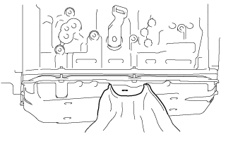
Note
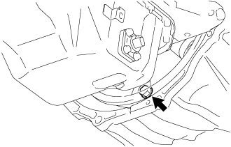
When removing the overflow plug, automatic transmission fluid may enter through the gap in the automatic transmission oil pan sub-assembly. Therefore, insert cloth between the gap in the automatic transmission oil pan sub-assembly as shown in the illustration to prevent the entry of automatic transmission fluid.
-
Lift the vehicle.
Note
Set the vehicle on a lift so that the vehicle is kept level when it is lifted up (make sure that the tilt angle from the front to rear of the vehicle is within +/-1°).
-
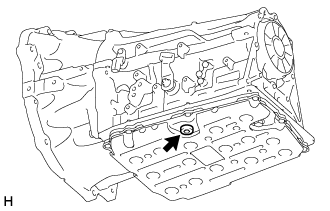
Using a 5 mm hexagon socket wrench, remove the overflow plug and gasket from the automatic transmission assembly.
CAUTION:
Be careful as the automatic transmission fluid coming out of the overflow hole is hot.
-
Check the amount of automatic transmission fluid that comes out of the overflow hole.
-
If the amount of automatic transmission fluid that comes out of the overflow hole is large, proceed to step [*1].
-
If no automatic transmission fluid comes out of the overflow hole, proceed to step [*2].
Note
If only a small amount of automatic transmission fluid (approximately 5 cc) comes out of the overflow hole, then only automatic transmission fluid remaining in the overflow tube of overflow hole has come out. This is not considered to be overflow.
-
-
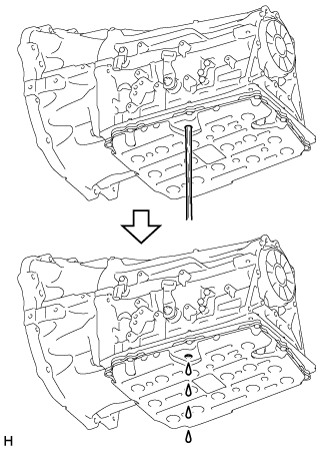
If the amount of automatic transmission fluid that comes out of the overflow hole is large, wait until the automatic transmission fluid flow slows and only drips come out. [*1]
Tech Tips
The automatic transmission fluid flow will not stop completely because the automatic transmission fluid continues to expand as its temperature increases.
-
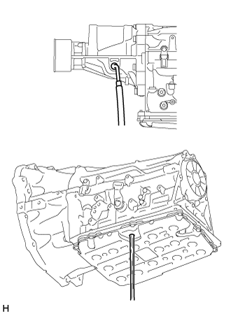
If no automatic transmission fluid comes out of the overflow hole, remove the refill plug and O-ring. Then add automatic transmission fluid to the refill hole until it flows out of the overflow hole. Wait until the automatic transmission fluid flow slows and only drips come out. [*2]
Note
-
Use Toyota Genuine ATF WS.
-
Be sure to add automatic transmission fluid slowly. If automatic transmission fluid is added quickly, the automatic transmission fluid may hit internal parts and bounce back, resulting in automatic transmission fluid coming out of the refill hole.
-
-
Wait until the automatic transmission fluid flow slows and only drips come out.
Tech Tips
The automatic transmission fluid flow will not stop completely because the automatic transmission fluid continues to expand as its temperature increases.
-
Using a 5 mm hexagon socket wrench, install a new gasket and the overflow plug to the automatic transmission assembly.
- Torque:
- 20 N*m { 204 kgf*cm, 15 ft.*lbf }
-
Install a new O-ring and the refill plug to the automatic transmission assembly.
- Torque:
- 39 N*m { 400 kgf*cm, 29 ft.*lbf }
-
Lower the vehicle.
-
Turn the ignition switch off.
Tech Tips
Turning the ignition switch off exits automatic transmission fluid temperature detection mode.
-
Disconnect the GTS from the DLC3 (when using the GTS).
-
-
INSPECT SHIFT LEVER POSITION
-
Переключая передачу только из положения P при включенном зажигании, нажмите педаль тормоза.
-
Убедитесь, что рычаг переключения передач движется плавно и перемещается под умеренным усилием.
-
Запустив двигатель, убедитесь, что при переключении рычага из положения N в положение D автомобиль двигается вперед, а при переключении в положение R - назад.
-
-
ADJUST SHIFT LEVER POSITION
-
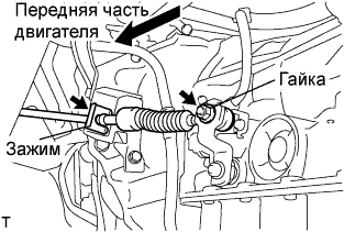
Снимите фиксатор, отверните гайку и отсоедините трос механизма переключения передач в сборе от рычага приводного вала и кронштейна троса механизма переключения передач № 1.
-
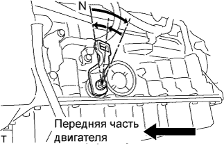
Поверните рычаг приводного вала до упора по часовой стрелке, а затем верните его на 2 метки в обратном направлении в положение N.
-
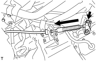
Установите рычаг переключения передач в положение N, слегка нажимая на него в направлении положения R, и установите его.
- Torque:
- 15 Н*м { 150 кгс*см, 11 фунт-сила-футов }
Note
Затяните гайку, чтобы исключить смешение деталей.
-
Проверьте режим работы и правильность работы.
-
-
INSPECT FOR EXHAUST GAS LEAK
-
If gas is leaking, tighten the areas necessary to stop the leak. Replace damaged parts as necessary.
-
-
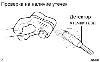
INSPECT FOR REFRIGERANT LEAK
-
После заправки газообразного хладагента с помощью галоидного течеискателя проверьте, нет ли утечек хладагента.
-
Выполните испытание с соблюдением описанных ниже условий:
-
Выключите двигатель.
-
Обеспечьте хорошую вентиляцию (детектор утечки газа может реагировать на летучие газы, не являющиеся хладагентом, - такие, как пары бензина и отработавшие газы).
-
Испытание необходимо выполнить 2 или 3 раза.
-
Убедитесь, что в системе охлаждения осталось некоторое количество хладагента.
Показания при выключенном компрессоре: примерно 392-588 кПа (4-6 кгс/см2, 57-85 фунтов на кв. дюйм)
-
-
С помощью детектора утечки газа проверьте, нет ли утечки из трубопровода хладагента.
-
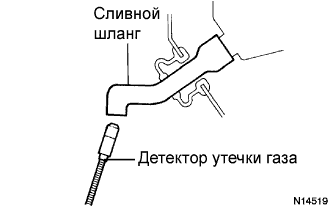
Расположите выключенный детектор утечки газа рядом со сливным шлангом.
Tech Tips
-
После остановки электродвигателя вентилятора не включайте блок охлаждения, по крайней мере, в течение 15 мин.
-
Располагайте датчик детектора утечки газа под сливным шлангом.
-
Расположив детектор утечки газа рядом со сливным шлангом, убедитесь, что он не реагирует на летучие газы.
Если такой реакции избежать не удается, автомобиль необходимо поднять.
-
-
Если в сливном шланге утечка газа не обнаруживается, снимите блок управления электродвигателем вентилятора с блока охлаждения. Затем вставьте датчик детектора утечки газа в блок и выполните испытание.
-
Отсоедините разъем контактного датчика давления и оставьте его в таком состоянии приблизительно на 20 мин. Поднесите детектор утечки газа к контактному датчику давления и выполните испытание.
-
-
INSTALL TRANSMISSION SERVICE HOLE COVER SUB-ASSEMBLY
-
Install the transmission service hole cover sub-assembly to the body with the 4 bolts.
- Torque:
- 7.0 N*m { 71 kgf*cm, 62 in.*lbf }
-
Return the carpet to its original position and attach the clips.
-
Connect the front center seat belt assembly RH and front center seat lap type belt assembly with the 2 bolts.
- Torque:
- 42 N*m { 428 kgf*cm, 31 ft.*lbf }
-
Install the 2 seat belt anchor covers.
-
-
INSTALL ENGINE SERVICE HOLE SUB COVER SUB-ASSEMBLY
-
Install the engine service hole sub cover sub-assembly with the 5 bolts.
- Torque:
- 13 N*m { 133 kgf*cm, 10 ft.*lbf }
-
Return the floor carpet to its original position.
-
-
INSTALL FRONT DOOR SCUFF PLATE RH
-
INSTALL FRONT SEAT ASSEMBLY RH
-
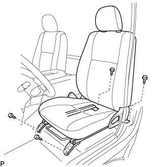
Подсоедините разъем замка ремня безопасности переднего сиденья в сборе и установите переднее сиденье в сборе.
-
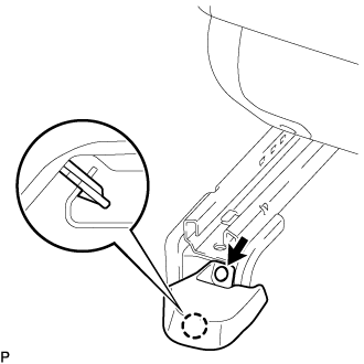
Совместите штырь регулятора переднего сиденья в сборе с отверстиями в кузове.
-
Сдвиньте переднее сиденье в сборе в крайнее заднее положение.
Note
Убедитесь, что переднее сиденье в сборе надежно зафиксировано.
-
Предварительно затяните 2 болта на передней стороне переднего сиденья в сборе.
-
Выдвиньте переднее сиденье в сборе до упора вперед.
Note
Убедитесь, что переднее сиденье в сборе надежно зафиксировано.
-
Предварительно затяните 2 болта на задней стороне переднего сиденья в сборе.
-
Сдвиньте переднее сиденье в сборе в крайнее заднее положение.
Note
Убедитесь, что переднее сиденье в сборе надежно зафиксировано.
-
Полностью затяните 2 болта на передней стороне переднего сиденья в сборе, сначала наружный, а затем внутренний.
- Torque:
- 39 Н*м { 398 кгс*см, 29 фунт-сила-футов }
-
Выдвиньте переднее сиденье в сборе до упора вперед.
Note
Убедитесь, что переднее сиденье в сборе надежно зафиксировано.
-
Полностью затяните 2 болта на задней стороне переднего сиденья в сборе, сначала наружный, а затем внутренний.
- Torque:
- 39 Н*м { 398 кгс*см, 29 фунт-сила-футов }
-
-
INSTALL SEAT TRACK COVER LH
-
Введите в зацепление захват и установите новый щиток направляющей левого сиденья и закрепите новым фиксатором.
-
-
INSPECT ENGINE IDLE SPEED
-
Warm up and stop the engine.
-
When using the GTS:
Tech Tips
-
For more information about the GTS, refer to its operator's manual.
-
If the GTS is not available, use a tachometer as a substitute.
-
Connect the GTS to the DLC3.
-
Start the engine and idle it.
-
Enter the following menus: Powertrain / Engine and ECT / Data List / Engine Speed.
Standard idle speed 650 to 750 rpm
-
-
When not using the GTS:
-
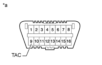
Text in Illustration *a Front view of DLC3 Connect a tester probe of a tachometer to terminal 9 (TAC) of the DLC3 with SST.
- SST
- 09843-18040
-
Start the engine and idle it.
-
-
Inspect the engine idle speed.
Standard idle speed 650 to 750 rpm Note
-
Turn all the electrical systems and A/C off.
-
When checking the idle speed, move the shift lever to neutral.
-
-
Turn the ignition switch off.
-
Disconnect the GTS or tachometer tester probe from the DLC3.
-
-
INSPECT MAXIMUM SPEED
-
Start the engine.
-
Fully depress the accelerator pedal.
-
Check the maximum engine speed.
Maximum engine speed 4450 to 4750 rpm
-
-
INSPECT AND ADJUST FRONT WHEEL ALIGNMENT
-
INSPECT ABS SPEED SENSOR SIGNAL
Для моделей с VSC (см. стр. Click here). Для моделей без VSC (см. стр. Click here).