POWER DOOR LOCK CONTROL SYSTEM SYSTEM DIAGRAM
Power Door Lock Control System (for LHD)
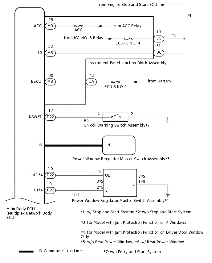
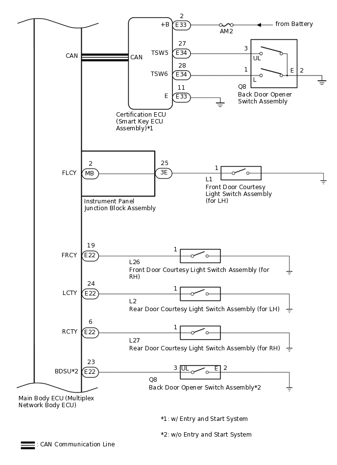
Table 1. Communication Table Sender
Receiver
Signal
Line
Certification ECU (Smart Key ECU Assembly)*1
Main Body ECU (Multiplex Network Body ECU)
Back door opener switch signal
CAN
Power Window Regulator Master Switch Assembly*2
Main Body ECU (Multiplex Network Body ECU)
Door control switch signal
LIN
*1: w/ Entry and Start System
*2: for Model with Jam Protection Function on 4 Windows
Power Door Lock Control System (for RHD)
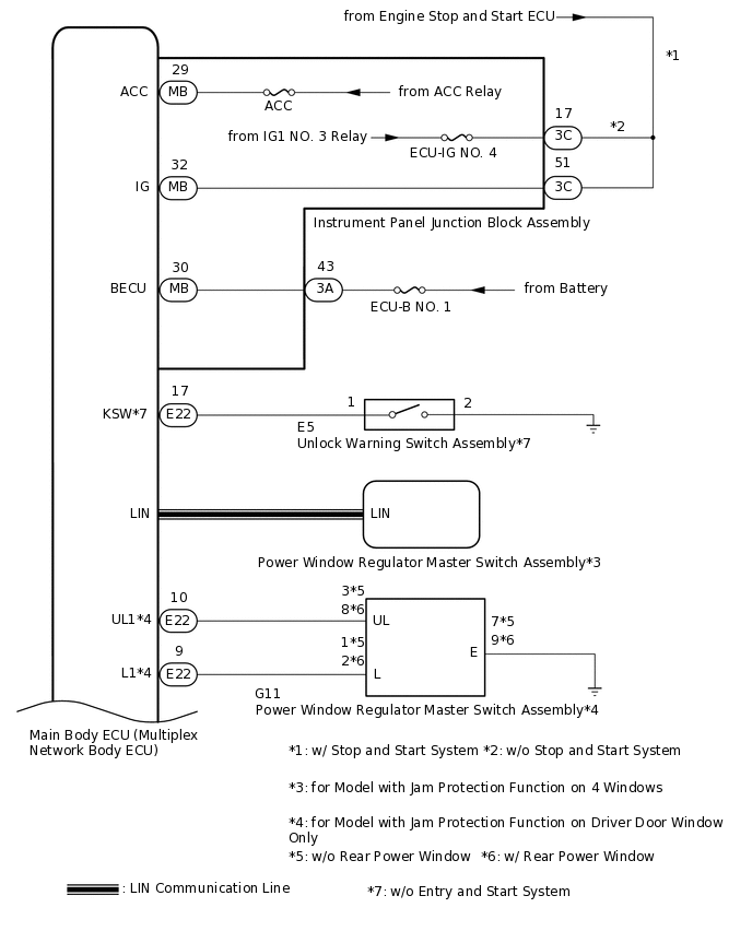

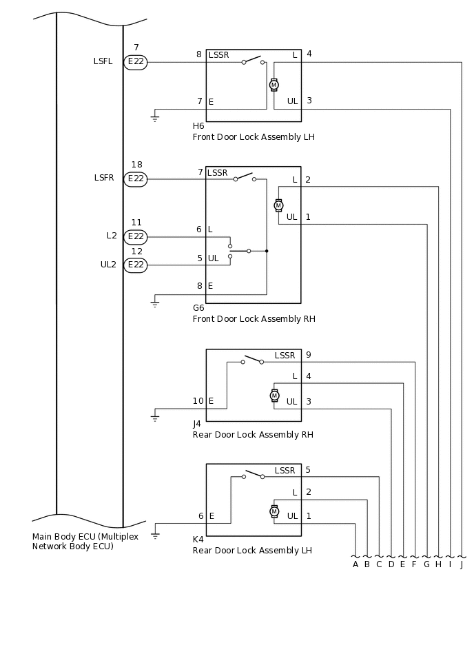
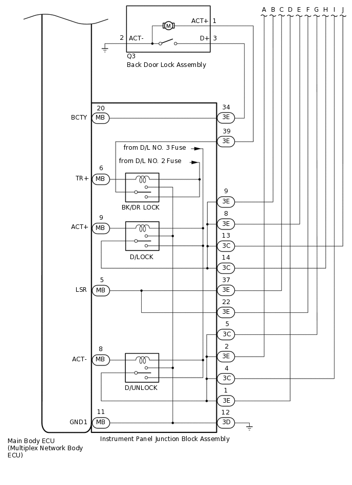
Table 2. Communication Table Sender
Receiver
Signal
Line
Certification ECU (Smart Key ECU Assembly)*1
Main Body ECU (Multiplex Network Body ECU)
Back door opener switch signal
CAN
Power Window Regulator Master Switch Assembly*2
Main Body ECU (Multiplex Network Body ECU)
Door control switch signal
LIN
*1: w/ Entry and Start System
*2: for Model with Jam Protection Function on 4 Windows
Double Locking System
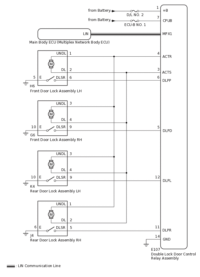
Table 3. Communication Table Sender
Receiver
Signal
Line
Double Lock Door Control Relay Assembly
Main Body ECU (Multiplex Network Body ECU)
Double lock position switch signal
LIN
Main Body ECU (Multiplex Network Body ECU)
Double Lock Door Control Relay Assembly
Double lock set/unset request Signal
LIN