STEERING PAD SWITCH INSPECTION
PROCEDURE
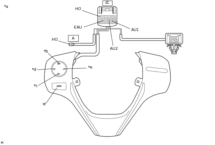
INSPECT STEERING PAD SWITCH ASSEMBLY (Type A)
Measure the resistance according to the value(s) in the table below.
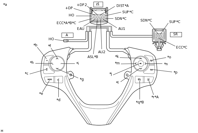
*A
w/ Lane Departure Alert System
*B
w/ Speed Limiter System
*C
w/ Shift Paddle Switch
-
-
*a
Component without harness connected
(Steering Pad Switch Assembly)
*b
Volume+
*c
Volume-
*d
Voice
*e
MODE
*f
Seek+
*g
Seek-
*h
Off Hook
*i
On Hook
*j
Enter
*k
Up
*l
Down
*m
Left
*n
Right
*o
Back
*p
TRIP
*q
Speed limiter
*r
Lane departure alert
Standard Resistance
Tester Connection
Condition
Specified Condition
z1-1 (HO) - A-1 (HO)
Always
Below 2.5 Ω
z1-11 (AU1) - z1-8 (EAU)
No switch pushed
95 to 105 kΩ
Seek+ switch pushed
Below 2.5 Ω
Seek- switch pushed
313 to 345 Ω
Volume+ switch pushed
950 to 1050 Ω
Volume- switch pushed
2955 to 3265 Ω
z1-10 (AU2) - z1-8 (EAU)
No switch pushed
95 to 105 kΩ
MODE switch pushed
Below 2.5 Ω
On hook switch pushed
313 to 345 Ω
Off hook switch pushed
950 to 1050 Ω
Voice switch pushed
2955 to 3265 Ω
z1-2 (+DP) - z1-8 (EAU)
No switch pushed
95 to 105 kΩ
Enter switch pushed
Below 2.5 Ω
TRIP switch pushed
313 to 345 Ω
Back switch pushed
950 to 1050 Ω
z1-3 (+DP2) - z1-8 (EAU)
No switch pushed
95 to 105 kΩ
Left switch pushed
Below 2.5 Ω
UP switch pushed
313 to 345 Ω
Down switch pushed
950 to 1050 Ω
Right switch pushed
2955 to 3265 Ω
z1-4 (DIST) - z1-7 (ECC)*1
No switch pushed
1 MΩ or higher
Lane departure alert switch pushed
Below 2.5 Ω
z1-9 (ASL) - z1-7 (ECC)*2
No switch pushed
1 MΩ or higher
Speed limiter switch pushed
Below 2.5 Ω
z1-6 (SUP) - SR-2 (SUP)*3
Always
Below 2.5 Ω
z1-7 (ECC) - SR-7 (ECC)*3
Always
Below 2.5 Ω
z1-12 (SDN) - SR-3 (SDN)*3
Always
Below 2.5 Ω
*1: w/ Lane Departure Alert System
*2: w/ Speed Limiter System
*3: w/ Shift Paddle Switch
Tip:If the result is not as specified, replace the steering pad switch assembly.
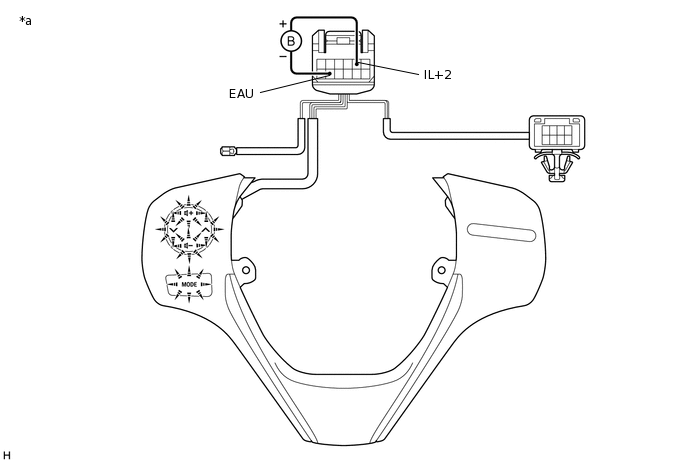
Check the illumination.
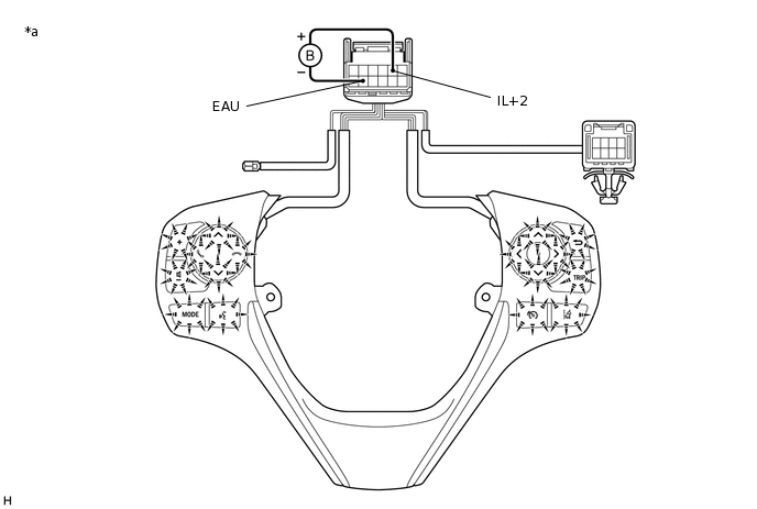
*a
Component without harness connected
(Steering Pad Switch Assembly)
-
-
Connect a positive (+) lead from the battery to terminal 5 (IL+2) and a negative (-) lead to terminal 8 (EAU) of the steering pad switch assembly connector.
Check that the steering pad switch assembly illumination illuminates.
OK
The steering pad switch assembly illumination illuminates.
Tip:If the result is not as specified, replace the steering pad switch assembly.
INSPECT STEERING PAD SWITCH ASSEMBLY (Type B)
Measure the resistance according to the value(s) in the table below.
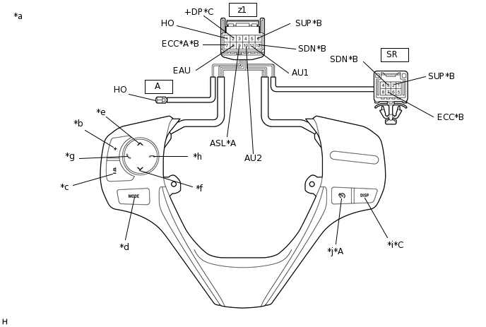
*A
w/ Speed Limiter System
*B
w/ Shift Paddle Switch
*C
w/ DISP Switch
-
-
*a
Component without harness connected
(Steering Pad Switch Assembly)
*b
Volume+
*c
Volume-
*d
MODE
*e
Seek+
*f
Seek-
*g
Off Hook
*h
On Hook
*i
DISP
*j
Speed limiter
Standard Resistance
Tester Connection
Condition
Specified Condition
z1-1 (HO) - A-1 (HO)
Always
Below 2.5 Ω
z1-11 (AU1) - z1-8 (EAU)
No switch pushed
95 to 105 kΩ
Seek+ switch pushed
Below 2.5 Ω
Seek- switch pushed
313 to 345 Ω
Volume+ switch pushed
950 to 1050 Ω
Volume- switch pushed
2955 to 3265 Ω
z1-10 (AU2) - z1-8 (EAU)
No switch pushed
95 to 105 kΩ
MODE switch pushed
Below 2.5 Ω
On hook switch pushed
313 to 345 Ω
Off hook switch pushed
950 to 1050 Ω
z1-2 (+DP) - z1-8 (EAU)*1
No switch pushed
95 to 105 kΩ
DISP switch pushed
Below 2.5 Ω
z1-9 (ASL) - z1-7 (ECC)*2
No switch pushed
1 MΩ or higher
Speed limiter switch pushed
Below 2.5 Ω
z1-6 (SUP) - SR-2 (SUP)*3
Always
Below 2.5 Ω
z1-7 (ECC) - SR-7 (ECC)*3
Always
Below 2.5 Ω
z1-12 (SDN) - SR-3 (SDN)*3
Always
Below 2.5 Ω
*1: w/ DISP Switch
*2: w/ Speed Limiter System
*3: w/ Shift Paddle Switch
Tip:If the result is not as specified, replace the steering pad switch assembly.
Check the illumination.
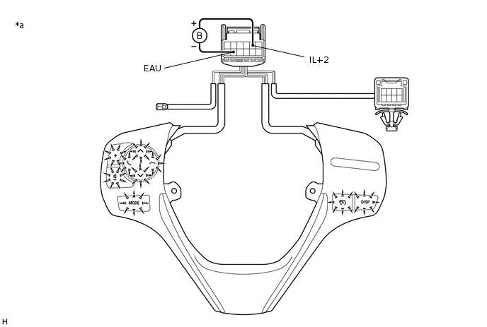
*a
Component without harness connected
(Steering Pad Switch Assembly)
-
-
Connect a positive (+) lead from the battery to terminal 5 (IL+2) and a negative (-) lead to terminal 8 (EAU) of the steering pad switch assembly connector.
Check that the steering pad switch assembly illumination illuminates.
OK
The steering pad switch assembly illumination illuminates.
Tip:If the result is not as specified, replace the steering pad switch assembly.
INSPECT STEERING PAD SWITCH ASSEMBLY (Type C)
Measure the resistance according to the value(s) in the table below.
*a
Component without harness connected
(Steering Pad Switch Assembly)
*b
Volume+
*c
Volume-
*d
Seek-
*e
Seek+
*f
MODE
Standard Resistance
Tester Connection
Condition
Specified Condition
z1-1 (HO) - A-1 (HO)
Always
Below 2.5 Ω
z1-11 (AU1) - z1-8 (EAU)
No switch pushed
95 to 105 kΩ
Seek+ switch pushed
Below 2.5 Ω
Seek- switch pushed
313 to 345 Ω
Volume+ switch pushed
950 to 1050 Ω
Volume- switch pushed
2955 to 3265 Ω
z1-10 (AU2) - z1-8 (EAU)
No switch pushed
95 to 105 kΩ
MODE switch pushed
Below 2.5 Ω
Tip:If the result is not as specified, replace the steering pad switch assembly.
Check the illumination.
*a
Component without harness connected
(Steering Pad Switch Assembly)
-
-
Connect a positive (+) lead from the battery to terminal 5 (IL+2) and a negative (-) lead to terminal 8 (EAU) of the steering pad switch assembly connector.
Check that the steering pad switch assembly illumination illuminates.
OK
The steering pad switch assembly illumination illuminates.
Tip:If the result is not as specified, replace the steering pad switch assembly.
INSPECT STEERING PAD SWITCH ASSEMBLY (Type D)
Measure the resistance according to the value(s) in the table below.
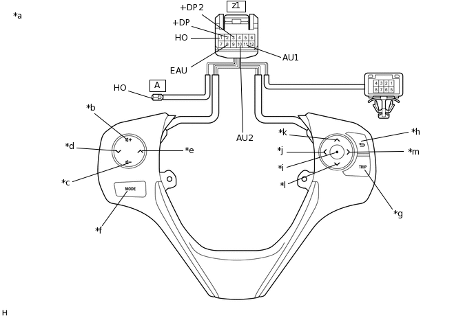
*a
Component without harness connected
(Steering Pad Switch Assembly)
*b
Volume+
*c
Volume-
*d
Seek-
*e
Seek+
*f
MODE
*g
TRIP
*h
Back
*i
Enter
*j
Left
*k
Up
*l
Down
*m
Right
-
-
Standard Resistance
Tester Connection
Condition
Specified Condition
z1-1 (HO) - A-1 (HO)
Always
Below 2.5 Ω
z1-11 (AU1) - z1-8 (EAU)
No switch pushed
95 to 105 kΩ
Seek+ switch pushed
Below 2.5 Ω
Seek- switch pushed
313 to 345 Ω
Volume+ switch pushed
950 to 1050 Ω
Volume- switch pushed
2955 to 3265 Ω
z1-10 (AU2) - z1-8 (EAU)
No switch pushed
95 to 105 kΩ
MODE switch pushed
Below 2.5 Ω
z1-2 (+DP) - z1-8 (EAU)
No switch pushed
95 to 105 kΩ
Enter switch pushed
Below 2.5 Ω
TRIP switch pushed
313 to 345 Ω
Back switch pushed
950 to 1050 Ω
z1-3 (+DP2) - z1-8 (EAU)
No switch pushed
95 to 105 kΩ
Left switch pushed
Below 2.5 Ω
Up switch pushed
313 to 345 Ω
Down switch pushed
950 to 1050 Ω
Right switch pushed
2955 to 3265 Ω
Tip:If the result is not as specified, replace the steering pad switch assembly.
Check the illumination.
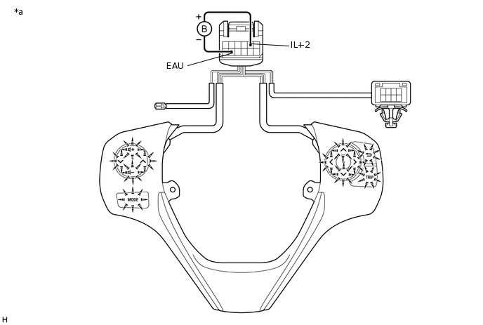
*a
Component without harness connected
(Steering Pad Switch Assembly)
-
-
Connect a positive (+) lead from the battery to terminal 5 (IL+2) and a negative (-) lead to terminal 8 (EAU) of the steering pad switch assembly connector.
Check that the steering pad switch assembly illumination illuminates.
OK
The steering pad switch assembly illumination illuminates.
Tip:If the result is not as specified, replace the steering pad switch assembly.