FRONT LOWER SUSPENSION ARM INSTALLATION
CAUTION / NOTICE / HINT
Use the same procedure for the RH and LH sides.
The procedure listed below is for the LH side.
PROCEDURE
TEMPORARILY INSTALL FRONT NO. 1 LOWER SUSPENSION ARM SUB-ASSEMBLY LH
Position the front suspension crossmember on a level surface.
-
Temporarily install the front lower suspension arm LH to the front suspension crossmember with the 2 bolts and nut.
Note:Because the nut has its own stopper, do not turn the nut. Tighten the bolt with the nut fixed in place.
INSTALL FRONT SUSPENSION CROSSMEMBER SUB-ASSEMBLY
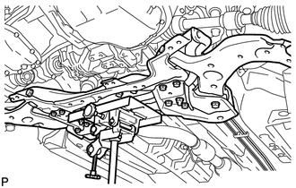
Support the front suspension crossmember with a transmission jack.
Install the front suspension crossmember with the 4 bolts and 2 nuts, and tighten the bolts and nuts in several steps while alternately inserting SST into the left and right reference holes of the front suspension crossmember.
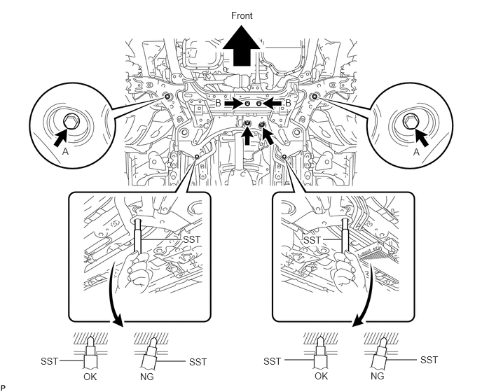
09670-00020
for bolt A
137 N*m
1397 kgf*cm
101 ft.*lbf
for bolt B
95 N*m
969 kgf*cm
70 ft.*lbf
for nut
95 N*m
969 kgf*cm
70 ft.*lbf
-
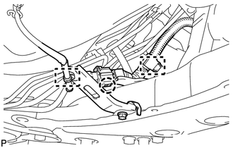
Attach the 2 clamps and claw to connect the oxygen sensor wire to the front suspension crossmember.
INSTALL FRONT SUSPENSION MEMBER REAR BRACE LH
-
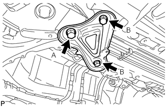
Install the rear brace with the 3 bolts.
for bolt A
137 N*m
1397 kgf*cm
101 ft.*lbf
for bolt B
93 N*m
948 kgf*cm
69 ft.*lbf
-
INSTALL FRONT SUSPENSION MEMBER REAR BRACE RH
Tip:Perform the same procedure as for the LH side.
INSTALL FRONT SUSPENSION MEMBER REINFORCEMENT LH
-
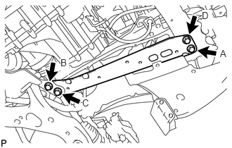
Install the reinforcement with the 4 bolts.
99 N*m
1010 kgf*cm
73 ft.*lbf
Note:Tighten the bolts in the order of C, B, D and A.
-
INSTALL FRONT SUSPENSION MEMBER REINFORCEMENT RH
-
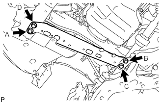
Install the reinforcement with the 4 bolts.
99 N*m
1010 kgf*cm
73 ft.*lbf
Note:Tighten the bolts in the order of C, B, D and A.
-
INSTALL FRONT LOWER ENGINE MOUNTING BRACKET REINFORCEMENT
CONNECT FRONT NO. 1 LOWER SUSPENSION ARM SUB-ASSEMBLY LH
CONNECT FRONT NO. 1 LOWER SUSPENSION ARM SUB-ASSEMBLY RH
Tip:Perform the same procedure as the LH side.
CONNECT TIE ROD END SUB-ASSEMBLY LH
CONNECT TIE ROD END SUB-ASSEMBLY RH
Tip:Perform the same procedure as for the LH side.
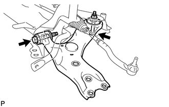
CONNECT FRONT STABILIZER LINK ASSEMBLY LH
-
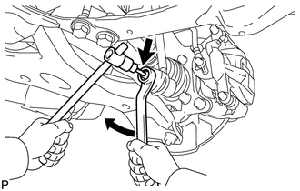
Connect the front stabilizer link to the front stabilizer bar with the nut.
74 N*m
755 kgf*cm
55 ft.*lbf
Tip:If the ball joint turns together with the nut, use a 6 mm hexagon wrench to hold the stud bolt.
-
CONNECT FRONT STABILIZER LINK ASSEMBLY RH
Tip:Perform the same procedure as for the LH side.
INSTALL NO. 1 STEERING COLUMN HOLE COVER SUB-ASSEMBLY
CONNECT NO. 2 STEERING INTERMEDIATE SHAFT ASSEMBLY
INSTALL COLUMN HOLE COVER SILENCER SHEET
INSTALL NO. 2 ENGINE UNDER COVER
INSTALL REAR ENGINE UNDER COVER LH
Install the under cover with the 5 clips.
INSTALL REAR ENGINE UNDER COVER RH
Tip:Perform the same procedure as for the LH side.
INSTALL FRONT WHEELS
103 N*m
1050 kgf*cm
76 ft.*lbf
STABILIZE SUSPENSION
Lower the vehicle.
Bounce the vehicle up and down at the corners several times to stabilize the suspension.
INSTALL CENTER NO. 4 ENGINE UNDER COVER
INSTALL NO. 1 ENGINE UNDER COVER (for 1ZR-FAE, 2ZR-FAE)
INSTALL NO. 1 ENGINE UNDER COVER (for 1WW)
TIGHTEN FRONT NO. 1 LOWER SUSPENSION ARM SUB-ASSEMBLY LH
-
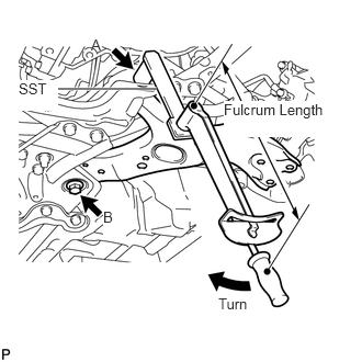
Using SST, tighten bolt A.
09961-01270
without SST
233 N*m
2376 kgf*cm
172 ft.*lbf
with SST
172 N*m
1755 kgf*cm
127 ft.*lbf
Note:Because the nut has its own stopper, do not turn the nut. Tighten the bolt with the nut fixed in place.
Use a torque wrench with a fulcrum length of 425 mm (1.39 ft.).
This torque value is effective when SST is parallel to the torque wrench.
The final torque must be applied under standard vehicle height conditions.
Tighten bolt B.
214 N*m
2182 kgf*cm
158 ft.*lbf
-
INSPECT AND ADJUST FRONT WHEEL ALIGNMENT
Inspect and adjust the front wheel alignment (Click here).
ADJUST HEADLIGHT ASSEMBLY
for Halogen Headlight:
Adjust the headlight assembly (Click here).
for HID Headlight:
Adjust the headlight assembly (Click here).