SHIFT LEVER ASSEMBLY REASSEMBLY
PROCEDURE
INSTALL SHIFT LOCK RELEASE BUTTON
Coat the shift lock release button and compression spring with MP grease.
-
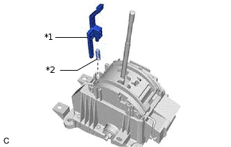
*1
Shift Lock Release Button
*2
Compression Spring
Install the shift lock release button and compression spring to the shift lock control unit assembly.
INSTALL POSITION INDICATOR SLIDE COVER
-
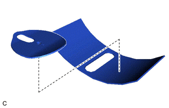
Install the No. 2 position indicator slide cover to the position indicator slide cover.
Install the position indicator slide cover to the shift lock control unit assembly.
-
INSTALL SHIFT LEVER POSITION SENSOR
-
Install the shift lever position sensor with the 3 screws.
1.4 N*m
14 kgf*cm
12 in.*lbf
-
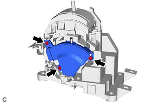
INSTALL POSITION INDICATOR LOWER HOUSING
-
Engage the 4 claws to install the position indicator lower housing to the shift lock control unit assembly.
-
INSTALL INDICATOR LIGHT WIRE SUB-ASSEMBLY
-
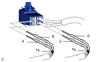
*a
Mark
Connect terminals 6 and 8 to the indicator light wire sub-assembly connector as shown in the illustration.
Connect terminals 2 and 4 to the indicator light wire sub-assembly connector as shown in the illustration.
-
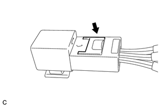
Lock the secondary lock.
-
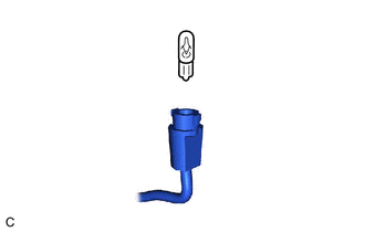
Install the bulb to the indicator light wire sub-assembly.
-
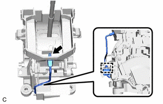
Connect the indicator light wire sub-assembly connector to the position indicator lower housing.
Connect the indicator light wire sub-assembly wire harness clamp to the shift lock control unit assembly
-
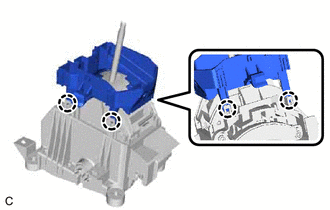
INSTALL FLOOR SHIFT POSITION INDICATOR HOUSING SUB-ASSEMBLY
-
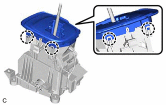
Engage the 4 claws to install the floor shift position indicator housing sub-assembly to the position indicator lower housing.
-