VEHICLE STABILITY CONTROL SYSTEM TERMINALS OF ECU
-
TERMINALS OF ECU
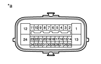
Text in Illustration *a Component without harness connected
(Skid Control ECU [Brake Actuator Assembly])
Terminal No. (Symbol) Terminal Description 1 (GND1) Skid control ECU ground 2 (STP) Stop light switch input 3 (IND) Slip indicator light output 4 (RL-) Rear wheel speed LH (-) signal input 5 (RL+) Rear wheel speed LH (+) power supply output 6 (FR-) Front wheel speed RH (-) signal input 7 (FR+) Front wheel speed RH (+) power supply output 8 (BRL) Brake warning light output 9 (EXI4)*1 L4 position switch input 10 (WA) ABS warning light output 12 (+BS) Solenoid relay power supply 13 (GND2) Pump motor ground 14 (CANL) CAN communication low line 15 (VSCW) VSC OFF indicator light output 16 (RR-) Rear wheel speed RH (-) signal input 17 (RR+) Rear wheel speed RH (+) power supply output 18 (FL-) Front wheel speed LH (-) signal input 19 (FL+) Front wheel speed LH (+) power supply output 20 (EXI)*1 4WD detection switch input 24 (BM) Motor relay power supply 25 (CANH) CAN communication high line 27 (FSW+) Brake pedal load sensing switch input 28 (EXI3) w/o Rear Differential Lock: IG power supply input
w/ Rear Differential Lock: Rear differential lock position switch signal input
29 (PKB) Parking brake switch input 30 (CSW) VSC OFF switch input 32 (P)*2 Park/neutral position switch signal input 33 (TS) Sensor check input 34 (IG1) ECU power supply
-
*1: for 4WD
-
*2: for Automatic Transmission
-
-
TERMINAL INSPECTION
-
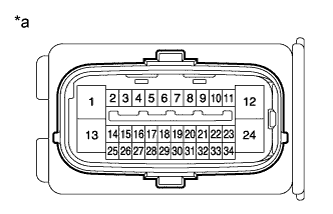
Text in Illustration *a Front view of wire harness connector
(to Skid Control ECU [Brake Actuator Assembly])
Disconnect the connector and measure the voltage or resistance according to the value(s) in the table below.
Tech Tips
The voltage cannot be measured with the connector connected to the skid control ECU (brake actuator assembly) as the connector is watertight.
Standard Terminal No. (Symbol) Wiring Color Terminal Description Condition Specified Condition S35-1 (GND1) - Body ground W-B - Body ground Skid control ECU ground Always Below 1 Ω S35-2 (STP) - Body ground G-W - Body ground Stop light switch input Brake pedal depressed → released 8 to 14 V
→ Below 1.5 V
S35-9 (EXI4)*1 - Body ground G-W - Body ground L4 position switch input
-
Ignition switch ON
-
Transfer shift position not L4
11 to 14 V S35-12 (+BS) - Body ground W-R - Body ground Solenoid relay power supply Always 11 to 14 V S35-13 (GND2) - Body ground W-B - Body ground Pump motor ground Always Below 1 Ω S35-20 (EXI)*1 - Body ground R-B - Body ground 4WD detection switch input
-
Ignition switch ON
-
Transfer shift position H2
11 to 14 V S35-24 (BM) - Body ground R - Body ground Motor relay power supply Always 11 to 14 V S35-27 (FSW+) - Body ground L - Body ground Brake pedal load sensing switch input Brake pedal depressed → released 950 to 1050 Ω → 203 to 223 Ω S35-28 (EXI3) - Body ground V - Body ground w/o Rear Differential Lock: IG power supply input
w/ Rear Differential Lock: Rear differential lock position switch signal input
-
Ignition switch ON
-
w/ Rear Differential Lock: Rear differential free
11 to 14 V S35-29 (PKB) - Body ground L-O - Body ground Parking brake switch input
-
Ignition switch ON
-
Parking brake lever pulled → released
Below 1 Ω → 10 kΩ or higher S35-30 (CSW) - Body ground R-L - Body ground VSC OFF switch input VSC OFF switch held → released Below 1 Ω → 10 kΩ or higher S35-32 (P)*2 - Body ground G-B - Body ground Park/neutral position switch signal input
-
Ignition switch ON
-
Shift lever not in P → Shift lever in P
Below 1 V
→ 11 to 14 V
S35-34 (IG1) - Body ground B - Body ground ECU power supply Ignition switch ON 11 to 14 V
-
*1: for 4WD
-
*2: for Automatic Transmission
-
-