WIRELESS DOOR LOCK CONTROL SYSTEM(w/ Entry and Start System) TERMINALS OF ECU
CHECK INSTRUMENT PANEL JUNCTION BLOCK ASSEMBLY AND MAIN BODY ECU (MULTIPLEX NETWORK BODY ECU)
Disconnect the MB main body ECU (multiplex network body ECU) connector.
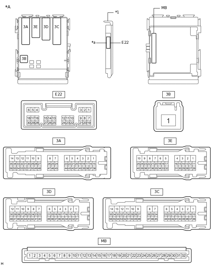
*A
Main Body ECU (Multiplex Network Body ECU) with 1 Connector
-
-
*1
Main Body ECU (Multiplex Network Body ECU)
-
-
*a
1 Connector
-
-
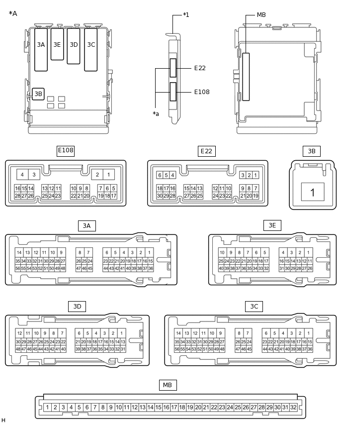
*A
Main Body ECU (Multiplex Network Body ECU) with 2 Connectors
-
-
*1
Main Body ECU (Multiplex Network Body ECU)
-
-
*a
2 Connectors
-
-
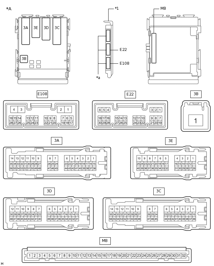
*A
Main Body ECU (Multiplex Network Body ECU) with 3 Connectors
-
-
*1
Main Body ECU (Multiplex Network Body ECU)
-
-
*a
3 Connectors
-
-
Measure the voltage and resistance according to the value(s) in the table below.
Tip:Measure the values on the wire harness side with the connectors disconnected.
Tester Connection
Wiring Color
Terminal Description
Condition
Specified Condition
MB-11 (GND1) - Body ground
-
Ground
Always
Below 1 Ω
MB-30 (BECU) - Body ground
-
Battery power supply
Always
11 to 14 V
MB-29 (ACC) - Body ground
-
ACC power supply
Engine switch on (ACC)
11 to 14 V
MB-29 (ACC) - Body ground
-
ACC power supply
Engine switch off
Below 1 V
MB-32 (IG) - Body ground
-
Engine switch power supply
Engine switch on (IG)
11 to 14 V
MB-32 (IG) - Body ground
-
Engine switch power supply
Engine switch off
Below 1 V
If the result is not as specified, there may be a malfunction in the wire harness.
Reconnect the MB main body ECU (multiplex network body ECU) connector.
Measure the voltage and check for pulses according to the value(s) in the table below.
Tester Connection
Wiring Color
Terminal Description
Condition
Specified Condition
3E-1 (ACT-) - Body ground
SB - Body ground
Door lock motor unlock drive output (all door)
Door control switch (power window regulator master switch assembly) or driver door key cylinder off
Below 1 V
3E-1 (ACT-) - Body ground
SB - Body ground
Door lock motor unlock drive output (all door)
Door control switch (power window regulator master switch assembly) or driver door key cylinder unlocked
11 to 14 V
3C-5 (ACT-) - Body ground
SB - Body ground
Door lock motor unlock drive output (all door)
Door control switch (power window regulator master switch assembly) or driver door key cylinder off
Below 1 V
3C-5 (ACT-) - Body ground
SB - Body ground
Door lock motor unlock drive output (all door)
Door control switch (power window regulator master switch assembly) or driver door key cylinder unlocked
11 to 14 V
3E-2 (ACT-) - Body ground
SB - Body ground
Door lock motor unlock drive output (all door)
Door control switch (power window regulator master switch assembly) or driver door key cylinder off
Below 1 V
3E-2 (ACT-) - Body ground
SB - Body ground
Door lock motor unlock drive output (all door)
Door control switch (power window regulator master switch assembly) or driver door key cylinder unlocked
11 to 14 V
3C-4 (ACT-) - Body ground
LG - Body ground
Door lock motor unlock drive output (all door)
Door control switch (power window regulator master switch assembly) or driver door key cylinder off
Below 1 V
3C-4 (ACT-) - Body ground
LG - Body ground
Door lock motor unlock drive output (all door)
Door control switch (power window regulator master switch assembly) or driver door key cylinder unlocked
11 to 14 V
3C-13 (ACT+) - Body ground
BE - Body ground
Door lock motor lock drive output (all doors)
Door control switch (power window regulator master switch assembly) or driver door key cylinder off
Below 1 V
3C-13 (ACT+) - Body ground
BE - Body ground
Door lock motor lock drive output (all doors)
Door control switch (power window regulator master switch assembly) or driver door key cylinder locked
11 to 14 V
3C-14 (ACT+) - Body ground
R - Body ground
Door lock motor lock drive output (all doors)
Door control switch (power window regulator master switch assembly) or driver door key cylinder off
Below 1 V
3C-14 (ACT+) - Body ground
R - Body ground
Door lock motor lock drive output (all doors)
Door control switch (power window regulator master switch assembly) or driver door key cylinder locked
11 to 14 V
3E-8 (ACT+) - Body ground
BE - Body ground
Door lock motor lock drive output (all doors)
Door control switch (power window regulator master switch assembly) or driver door key cylinder off
Below 1 V
3E-8 (ACT+) - Body ground
BE - Body ground
Door lock motor lock drive output (all doors)
Door control switch (power window regulator master switch assembly) or driver door key cylinder locked
11 to 14 V
3E-9 (ACT+) - Body ground
R - Body ground
Door lock motor lock drive output (all doors)
Door control switch (power window regulator master switch assembly) or driver door key cylinder off
Below 1 V
3E-9 (ACT+) - Body ground
R - Body ground
Door lock motor lock drive output (all doors)
Door control switch (power window regulator master switch assembly) or driver door key cylinder locked
11 to 14 V
3E-25 (FLCY) - Body ground
W - Body ground
Front door LH courtesy light switch input
Front door LH open
Below 1 V
3E-25 (FLCY) - Body ground
W - Body ground
Front door LH courtesy light switch input
Front door LH closed
Pulse generation
E22-19 (FRCY) - Body ground
V - Body ground
Front door RH courtesy light switch input
Front door RH open
Below 1 V
E22-19 (FRCY) - Body ground
V - Body ground
Front door RH courtesy light switch input
Front door RH closed
Pulse generation
E22-24 (LCTY) - Body ground
SB - Body ground
Rear door LH courtesy light switch input
Rear door LH open
Below 1 V
E22-24 (LCTY) - Body ground
SB - Body ground
Rear door LH courtesy light switch input
Rear door LH closed
Pulse generation
E22-6 (RCTY) - Body ground
LG - Body ground
Rear door RH courtesy light switch input
Rear door RH open
Below 1 V
E22-6 (RCTY) - Body ground
LG - Body ground
Rear door RH courtesy light switch input
Rear door RH closed
Pulse generation
E22-7 (LSFL) - Body ground
Y - Body ground
Front door LH unlock detection switch input
Front door LH unlocked
Below 1 V
E22-7 (LSFL) - Body ground
Y - Body ground
Front door LH unlock detection switch input
Front door LH locked
Pulse generation
E22-18 (LSFR) - Body ground
LG - Body ground
Front door RH unlock detection switch input
Front door RH unlocked
Below 1 V
E22-18 (LSFR) - Body ground
LG - Body ground
Front door RH unlock detection switch input
Front door RH locked
Pulse generation
3E-22 (LSR) - Body ground
Y - Body ground
Rear door RH unlock detection switch input
Rear door RH or LH unlocked
Below 1 V
3E-22 (LSR) - Body ground
Y - Body ground
Rear door RH unlock detection switch input
Rear door RH and LH locked
Pulse generation
3E-37 (LSR) - Body ground
Y - Body ground
Rear door LH unlock detection switch input
Rear door LH or RH unlocked
Below 1 V
3E-37 (LSR) - Body ground
Y - Body ground
Rear door LH unlock detection switch input
Rear door LH and RH locked
Pulse generation
3A-56 (BZR) - Body ground
L - Body ground
Wireless door lock buzzer signal
Wireless door lock buzzer off
Below 1 V
3A-56 (BZR) - Body ground
L - Body ground
Wireless door lock buzzer signal
Wireless door lock buzzer on
Pulse generation
If the result is not as specified, the main body ECU (multiplex network body ECU) or instrument panel junction block assembly may be malfunctioning.
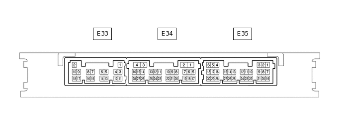
CHECK CERTIFICATION ECU (SMART KEY ECU ASSEMBLY)
Disconnect the E33 certification ECU (smart key ECU assembly) connector.
Measure the resistance and voltage according to the value(s) in the table below.
Tip:Measure the values on the wire harness side with the connectors disconnected.
Tester Connection
Wiring Color
Terminal Description
Condition
Specified Condition
E33-11 (E) - Body ground
W-B - Body ground
Ground
Always
Below 1 Ω
E33-2 (+B) - Body ground
L - Body ground
Battery power supply
Always
11 to 14 V
E33-10 (CUTB) - Body ground
LG - Body ground
Dark current cut fuse pin input signal
Always
11 to 14 V
If the result is not as specified, there may be a malfunction in the wire harness.
Reconnect the E33 certification ECU (smart key ECU assembly) connector.
Measure the voltage and check for pulses according to the value(s) in the table below.
Tester Connection
Wiring Color
Terminal Description
Condition
Specified Condition
E35-5 (IG) - E33-11 (E)
GR - W-B
Engine switch power supply
Engine switch on (IG)
11 to 14 V
Engine switch off
Below 1 V
E34-6 (CSEL) - E33-11 (E)
L - W-B
Communication channel switching circuit
Engine switch off and all door closed
Below 1 V → 4.5 to 6.0 V → Below 1 V
E34-17 (RDAM) - E33-11 (E)
Y - W-B
RF Signal input circuit
Engine switch off, all doors closed and electrical key transmitter sub-assembly switch not pressed → electrical key transmitter sub-assembly switch pressed
11 to 14 V pulse generation at regular intervals → pulse generation
E34-5 (RCO) - E33-11 (E)
V - W-B
Wireless tuner power supply output circuit
Engine switch off, all doors closed and electrical key transmitter sub-assembly switch not pressed → electrical key transmitter sub-assembly switch pressed
Below 1 V → 4.5 to 5.5 V
If the result is not as specified, the certification ECU (smart key ECU assembly) may be malfunctioning.
CHECK DOOR CONTROL RECEIVER
Disconnect the L35 door control receiver connector.

Measure the resistance according to the value(s) in the table below.
Tip:Measure the values on the wire harness side with the connectors disconnected.
Tester Connection
Wiring Color
Terminal Description
Condition
Specified Condition
L35-1 (GND) - Body ground
W-B - Body ground
Ground
Always
Below 1 Ω
If the result is not as specified, there may be a malfunction in the wire harness.
Reconnect the L35 door control receiver connector.
Measure the voltage according to the value(s) in the table below.
Tester Connection
Wiring Color
Terminal Description
Condition
Specified Condition
L35-2 (CSEL) - L35-1 (GND)
L - W-B
Communication channel switching circuit
Engine switch off and all door closed
Below 1 V → 4.5 to 6.0 V → Below 1 V
L35-5 (DATA) - L35-1 (GND)
Y - W-B
Data output
Engine switch off, all doors closed and electrical key transmitter sub-assembly switch not pressed → electrical key transmitter sub-assembly switch pressed
Below 1 V → 10 to 16 V → Below 1 V
L35-4 (+5) - L35-1 (GND)
V - W-B
Battery (power supply)
Engine switch off, all doors closed and electrical key transmitter sub-assembly switch not pressed → electrical key transmitter sub-assembly switch pressed
Below 1 V → 4.5 to 5.5 V
If the result is not as specified, the door control receiver may be malfunctioning.